Fully Custom Packet Collection
Fully Custom Message Collection is used for devices without ready-made collection plugins but whose communication rules can be described using fixed requests, frame segmentation, response matching, validation, and data offsets. The device plugin is named CustomPacketMaster, supporting TCP clients, TCP servers, UDP sessions, and serial channels.
Through protocol configuration, you can define full read requests, write requests with variable placeholders, four response framing rules, response attribution and success conditions, validation algorithms, and payload range. Device debugging can send full messages by HEX or text, displaying actual bytes sent, complete responses, time consumption, and error information.
Applicable Scenarios
| Scenarios | Descriptions |
|---|---|
| Vendor's Private Binary Protocol | Requests and responses have fixed structures, with data located in clear bytes or bit offsets. |
| Text Instruction Protocol | Messages can be generated according to specified character encodings and framed with terminators or fixed lengths. |
| Fixed Header Protocol | The header contains fields with one, two, or four bytes of length, which can be used to calculate the complete frame length. |
| Minimum Protocol | Each frame contains a clear start and end code. |
| Simple read/write protocol | Read uses fixed requests; writing packets only requires replacing one variable value. |
Protocols requiring login handshakes, multi-stage sessions, dynamic keys, encryption and decryption, compression, file transfer, or cross-message state machine should be developed as independent collection plugins. Custom message configuration does not execute arbitrary scripts.
Preparation Before Configuration
Before configuration, the following information should be confirmed from the device protocol manual, packet capture results, or vendor joint debugging documentation.
| Information | What needs to be confirmed |
|---|---|
| Communication link | Device uses TCP client, TCP server, UDP session, Or through local serial communication. |
| Full request | The complete HEX packet actually sent by each read command. |
| Frame Segmentation Rules | One of fixed package headers, minimum and stop intervals, terminators, or fixed length. |
| Response Attribution | The command word, station number, or transaction identifier used in the response to determine whether it belongs to the current request. |
| Success Condition | The status byte in the response that indicates success or failure. |
| Payload | Starting points and lengths of variable data in the complete response frame. |
| Validation Rules | Algorithms, computation intervals, checksum positions, byte order, and the writing method for requested checksum values. |
| Point Table | Variable name, data type, byte order, byte offset, optional bit offset, and read/write permissions. |
For the first joint debugging, it is recommended to configure only one read command and one to three variables. After confirming that message transmission, payload, and numerical parsing are all correct, extend the complete point table and write commands.
Create a New Channel
Log in to GatewayRuntime Web, go to "Development Configuration → Collection Configuration," and click "Channel Management → New."
- Fill in a unique and easily identifiable channel name.
- Depending on the device connection direction, select
TcpClient,TcpService,UdpSession, or serial port channel. - Fill in the remote address, binding address, or serial port parameters, and open the channel. Ordinary UDP active acquisition requires configuring the device's remote address.
- Set connection timeouts, cache timeouts, and maximum concurrency based on on-site network latency.
- Save the passage.
| Channel Type | Usage Conditions | Key Parameters |
|---|---|---|
TcpClient | GatewayRuntime Actively connects devices or protocol emulators. | Remote IP, port, and connection timeout. |
TcpService | device or DTU actively connects to GatewayRuntime. | Binding addresses, listening ports, client limits, and DTU identification rules. |
UdpSession | devices send and receive complete datagrams via UDP; Suitable for connectionless request response protocols. | Local binding address, remote device IP and port; DDP scenarios also require confirmation of terminal identification. |
| Serial Port | Devices communicate via local or mapped serial ports. | Serial slogan, baud rate, data bits, stop bits, and check bits. |
Under a UDP channel, a datagram must and can only contain one complete protocol frame. GatewayRuntime will not combine multiple UDP datagrams into one frame, nor will it accept the inclusion of a second frame within the same datagram. Inside datagrams, the protocol configuration still checks fixed package headers, starting and ending codes, end symbols, or fixed lengths. UDP itself does not guarantee packet arrival, order, or deduplication; devices and networks should allow request timeouts and retries according to the acquisition strategy.
Create a new device
Click "Device Management → New", complete the basic device information, then configure the plugin properties.
- "Equipment Name" should be filled with the unique name of the on-site equipment.
- For "Device Plugins," select
CustomPacketMaster. - "Link Channel" selects the channel created in the previous step.
- Set execution intervals and read/write timeouts according to on-site polling cycles.
- For TCP server or DDP UDP scenarios, fill in the
DTU IDaccording to the actual terminal registration identifier; Ordinary UDP uses a remote address configured by the channel. - Open "Plugin Properties" and click "Configure Protocol" under "Protocol Configuration."
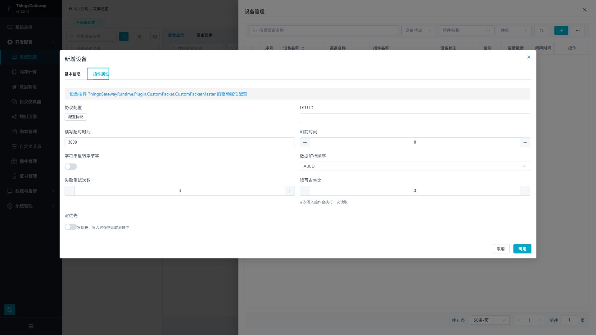
Configure Frame Segmentation
The "Frame Segmentation" page in protocol configuration determines how GatewayRuntime identifies a complete response frame from a TCP/serial port continuous byte stream or a single UDP datagram. Each device can only choose one frame splitting mode.
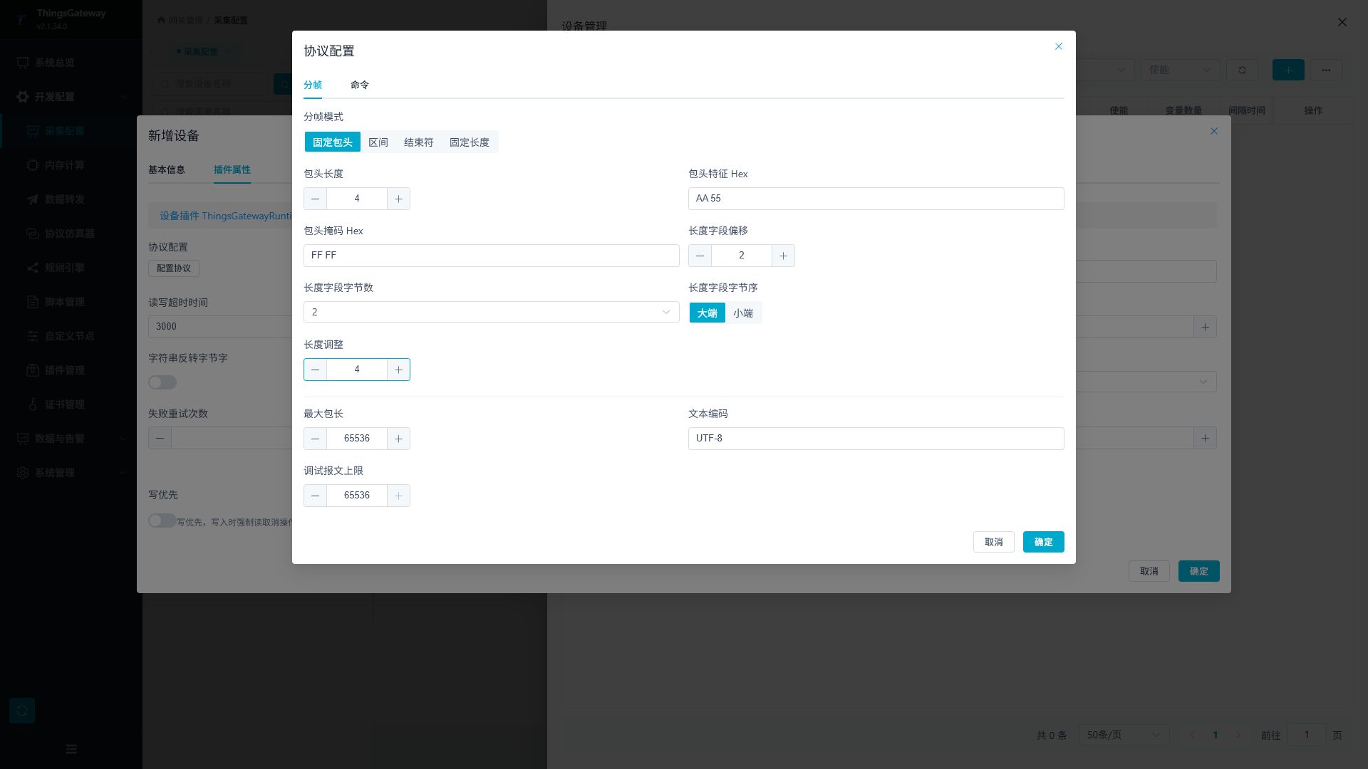
Fixed header
Fixed header mode is suitable for protocols containing length fields within the header. The full frame length is calculated as "length field decode value + length adjustment".
| Configuration Items | Description |
|---|---|
| Header Length | Number of fixed header bytes required to first determine the frame length. The length field must be fully within this range. |
| Header feature Hex | is used to identify fixed bytes at the frame starting point. It is recommended to fill out the form if there is link noise or packet sticking. |
| The Hex | of the head-to-head mask is as long as the head-to-head feature. Bit participation comparison with FF mask is for bits with 00 ignored. |
| Length field offset | The length field offsets relative to the first byte of the complete frame, starting from 0. |
| Length field byte count | Only allowed 1, 2, or 4. |
| Byte order of length fields | Select the large-ender or small-ender according to the protocol. |
| Length adjustment | The number of bytes needed to convert the length field value to the full frame length. When the length field already represents the full frame length, fill in 0. |
For example, the length field indicates the message body length. If the fixed packet header is 6 bytes, the length adjustment should be set to 6; When the length field represents the entire frame length, enter 0.
Interval
Interval mode starts by collecting bytes from the start code until it reaches the end code, and counts both the start and end codes into the complete frame.
| Configuration Item | Description |
|---|---|
| Start Code Hex | Identifies one or more bytes starting from a frame. |
| End code Hex | indicates one or more bytes at the end of a frame. |
| Minimum frame length | Candidate frames shorter than this length will not be valid responses. |
End Symbol
End Symbol mode collects bytes from the start of the current frame, and after encountering the specified end character, completes one frame. Suitable for text protocols or fixed-suffix protocols at the end of line breaks.
| Configuration Item | Description |
|---|---|
| The terminator Hex | one or more end bytes, for example, CRLF is 0D 0A. |
| Minimum Frame Length | Used to exclude exception frames with only an end character or insufficient length. |
Fixed length
Fixed length mode splits responses by constant byte count. This mode is only used when the device's response length is exactly the same each time.
| Configuration Items | Description |
|---|---|
| Fixed length | Total bytes per complete response frame. |
General Frame Segmentation Parameters
| Configuration Items | Description |
|---|---|
| Maximum Packet Length | Maximum byte count allowed per frame. It should cover the maximum on-site response, but do not increase it without basis. |
| Text Encoding | is used only for text debugging input and response text display, without changing the HEX request. |
| Debugging Message Limit | The maximum number of bytes allowed to be sent per device debugging, which cannot exceed the maximum package length. |
UDP is also limited by the size of a single IPv4 datagram. A standard UDP can have a maximum of 65,507 custom packets; DDP UDP requires a reserved 16-byte encapsulation, with a maximum of 65,491 bytes for custom packets. The actual allowable value is the minimum among the "maximum packet length," "debug message limit," and UDP transmission limit.
Configure Read Commands
Switch to the "Commands" page, click "Add Command," and create a unique command for each read request in the protocol.
- "Command Name" includes a name starting with English letters, which can include letters, numbers, underscores, and hyphens, such as
ReadStatus. - Enable "Read Command".
- "Read Request Hex" fills in the complete request packet that the device actually needs to receive.
- Configure the destination matching segment, successful matching segment, and payload range for read responses.
- When a response has a checksum value, start response checksum and fill in the algorithm and field positions.
Hex can contain spaces for reading, but it must be made up of complete bytes. For example 01 03 00 00 00 02 is valid, while odd hexadecimal characters or non-Hex characters are invalid.
Configure Write Commands
When variable writing is required, you can enable "Write Command" within the same command or a standalone command.
- "Write request template" fills in the Hex template completely, and places a
${value}where the variable value should appear. - Templates must and can only contain one
${value}, and content other than placeholders must be valid Hex. - If the device does not respond after writing, enable "Write Only Send".
- When you need to confirm the write result, turn off "Write only send" and configure the write response rules.
- When a request needs validation, configure "Request Checksum" and choose to overwrite the reserved field or append it to the end of the packet.
For example, 01 06 00 10 ${value} means the first five bytes are fixed, and the bytes after encoding are placed at the end of the packet. The actual number of bytes and byte order of ${value} are determined by the data type and parsing configuration of the variable.
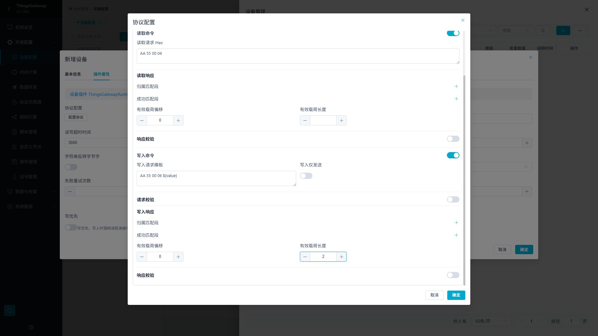
Writing will directly affect the field device. For the first test, select a point with no interlock risk and confirm that the equipment allows remote control. On-site authorization must be obtained before writing start/stop, reset, valve, motor, and process setpoints.
Configure response rules
Both reading responses and sending non-only write responses will first perform attribution, validation, and success checks. Only the read response requires intercepting variable data, so "payload offset" and "payload length" are only shown in the read response; The write response only confirms whether the device is executing correctly and does not return variable data.
| Configuration Item | Function |
|---|---|
| Attribute to Matching Segment | Check whether the complete response after framing belongs to the current request. Each segment consists of "offset, expected Hex, and optional mask Hex"; When configuring multiple segments, all must match. Leaving it blank will accept the first frame after splitting, and if the device reports asynchronously, it is prone to accidental reception. |
| Offset | starts from the first byte of the complete response frame, counting the byte position at 0. Both the attribution and success segments use this rule. |
| Expect one or more bytes of Hex | to appear from the specified offset, such as AA 55. |
| Mask Hex | optional, must be as long as the desired Hex. Compare bit by bit by (actual value & mask) == (expected value & mask); FF means all bits are involved in comparison, 00 means all bits are ignored, and leaving blank means exact matching. |
| Response Validation | Verify the validation values in the response to prevent corrupted messages from entering variable parsing. |
| Successful Match Segment | After the response has been attributed and verification passed, determine whether the device executed successfully. When configuring multiple segments, all must match; Leaving it blank means no status code is checked. |
| Payload offset | is used only to read responses. Start from the first byte of the complete response frame, starting with a data area counting 0. |
| Payload length | is used only for reading responses. The number of bytes in the data area to be returned for variable parsing; Leaving a blank means the payload offset is captured to the end of the frame. |
Attribute matching segments are usually configured with station numbers, command words, or transaction identifiers. Successful match segments are usually configured with status codes or exception codes. Byte offsets in variable addresses are calculated from the starting point of the captured payload, not from the start of the complete response frame.
For example, the device returns a full read response:
AA 55 10 00 02 01
can be configured according to the table below:
| Position | Configuration | Description |
|---|---|---|
| Affiliation Matching Segment 1 | Offset 0, Expect AA 55 | to confirm fixed response head. |
| Attribution matching segment 2 | offset 2, expecting 10 | to confirm that the command word belongs to this read. |
| Successfully match segment | offset 3, expecting 00 | device status code to be successful. |
| Payload | offset 4, length 2 | The final byte delivered to variable parsing is 02 01. |
If a state byte only requires the highest four bits to be the same, you can fill in the single-byte mask F0; The bottom four will be ignored. Do not replace "no configuration" with 00 masks, as this will exclude all bits of the desired byte from comparison.
Configuration Verification
After enabling verification, you can select Sum8,Xor8,Lrc8,Crc16Modbus, Crc16Ibm, and Crc16Ccitt. Turning off the validation switch means no validation rule is configured, so you do not need to select None.
Read requests always save the complete fixed Hex actually sent during debugging, including the existing CRC or cumulative sum at the end of the request, without separately configuring request validation. Request validation is only used to write templates: ${value} After being replaced by a byte of the actual variable, runtime needs to override or add the validation value according to the current full request. Response validation can be configured for both read and non-write responses.
| Configuration Items | Description |
|---|---|
| Algorithm | must be consistent with the device protocol manual. If you don't understand the algorithm, don't guess based on the last byte of the packet. |
| Calculation starting point | First byte offset of the checksum calculation. |
| Calculate length | Number of bytes involved in the calculation. If left blank, calculate from the "Calculation Starting Point" all the way up to before the check field; When using "add" in a request, it is counted all the way to the end of the original request before the addition. |
| Parity offset | The starting position of the parsum in the complete message in override mode. |
| Byte order | The order in which multi-byte checksums such as CRC are arranged in a message. |
| Write Method | Request validation can choose to overwrite reserved fields or add them; Response validation uses existing validation fields in the packet. |
Configure variable addresses
Use the following unique format for variable addresses:
ReadCommand@ByteOffset[.BitOffset][;write=WriteCommand]
| Section | Explanation |
|---|---|
ReadCommand | The command name for reading requests and reading response rules is configured. |
ByteOffset | The byte offset of the variable relative to the payload start must be a non-negative integer. |
BitOffset | Optional bit offset ranges from 0 to 7, commonly used for booleans. |
write=WriteCommand | Optionally write command. If not filled, write defaults using the write configuration in the read command. |
Example:
| Variable Address | Meaning |
|---|---|
ReadStatus@0 | Use ReadStatus to read and parse variables from byte 0 of the payload. |
ReadStatus@2.3 | Parse Boolean variables from the 3rd bit of byte 2 of the payload. |
ReadValue@4;write=WriteValue | Use ReadValue to read data starting from byte 4, and use WriteValue when writing. |
The data type, array length, byte order, string encoding, and expressions of variables are still set in the variable configuration. They must align with the real data layout in the payload.
Debug with Custom Messages
Open Development Configuration → Collection Configuration, select the CustomPacketMaster device, click More Functions, and open Debug.
- Select
Hexor "Text" input mode. - Choose "Send Only" or "Send and Wait".
- In text mode, select the character encoding consistent with the device.
- TCP server tunnels must select a target client from the online list. Regular UDP uses pre-configured remote addresses in the channel, while DDP UDP uses identified terminal endpoints.
- Enter the complete message and click Send.
- Check "Actual Send Hex". This value should match the input byte by byte.
- During "Send and Wait," continue to check the response Hex, response text, time, and error messages.
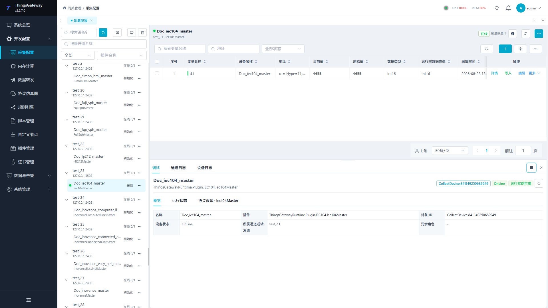
Debugging sends the full message entered by the user and does not automatically add packet headers, terminators, length fields, or checksums. If these bytes are needed, they must be fully filled in in the debug input. Debugging transmits and receivers use independent raw capture channels, not relying on current incorrect framing configurations; TCP/serial port aggregates responses based on received silence intervals, and UDP uses a non-null datagram as the response boundary; zero-length datagrams are not considered valid responses. Debugging still uses the channel bound to the current device; UDP remote addresses, serial port parameters, or TLS parameters cannot be temporarily modified.
| mode | behavior |
|---|---|
| only sends | packets to the channel and returns immediately afterward, without waiting for device response. |
| Send and wait for | packets to be written to the channel, then wait for a response via the original capture; TCP/serial port ends after a silence interval, and UDP receives a non-null datagram to terminate. |
"Send and wait" exclusively controls the target physical channel from the start of registering the original capture until receiving a response, timeout, or cancellation. If there are already periodic collection, variable writes, or other debugging requests on the channel, this debugging will wait for the previous request to end; Debugging that is canceled during the waiting period will not send packets or block subsequent requests. The capture session will close before the next request enters, preventing delayed responses from being misused by the next command.
Generate protocol configuration from debugging results
If protocol configuration is incorrect, original debugging can also be performed. The device pauses variable acquisition and uses the debug guidance protocol to maintain channel connections; The debugging page first collects samples through real requests and responses, then generates frame segmentation, reads commands, or writes templates according to user preferences, and finally verifies and confirms with the full editor and actual backend samples.
It is recommended to perform "send and wait" at least twice on the same request. Under safe and permissible conditions, allowing the data returned by the device to change—such as temperature, count values, or status—allows the system to more accurately identify possible payload ranges and stable response fields.
- Enter the full request on the debug page. For read or write commands that require confirmation of results, select "Send and Wait" and execute multiple successful exchanges; If the device does not receive a write response, select "Send only." TCP/serial port can adjust the reception silence interval as needed.
- Varying response length so that the fixed head length field has verifiable evidence; If the protocol uses start and stop or terminators, at least two complete responses should be collected. The page can retain up to 8 samples of the most recent successful responses.
- Click the Magic Wand button in the toolbar to open "Draft Agreement." A successful "send and wait" must include both the actual request and the complete response; A successful "send only" can directly generate the write send only command.
- Select "Read command" or "Write command" and enter the command name that matches the naming rules.
- In the "Frame Generation Method," select "Automatic Identification," "Retain Current Configuration," or a clear frame segmentation mode. If it is known that the equipment uses fixed wrapping heads, intervals, end symbols, or fixed lengths, the corresponding mode should be selected directly.
- Confirm payload, success status, and write value range according to actual protocols. Only when truly needed is "Automatic Generation of Matching Segments" enabled, and the maximum number of segments can be set; No generation by default; after enabling it, it can generate at most 1 segment by default.
- When the protocol contains validation, writing commands can enable "request validation," while reading or waiting for response commands can enable "response validation." Select algorithms, calculation ranges, checksum offsets, and byte order according to the device protocol manual; Write request validation also requires choosing override or addition.
- Click "Regenerate" and wait for the "Actual Sample Verification Passed" status to appear. If it fails, adjust the field according to the error prompt and regenerate it.
- Click "Full Review" to check the current frame configuration, command requests, response rules, and validation configurations. You can rename the command generated this time, and the system will continue to track it and validate it with the new name; If you delete the command corresponding to this sample, the draft will immediately become invalid. After closing the full editor, the system will verify again using the same actual sample.
- Click "Apply and restart device". After confirming, the system will write a draft into the latest protocol configuration for the device and restart the device according to the normal device update process.
| Draft configuration | Description |
|---|---|
| Number of comparable samples | Same length as the initial response, The number of responses that can be compared byte-byte. Samples with different response lengths will not participate in this range derivation. |
| Frame generation method | "Automatic Identification" selects a candidate in the order of interval, fixed package header, terminator, and fixed length evidence; "Keep current configuration" does not modify existing frame splits on the device; When explicit mode is selected, only that pattern is generated; no other boundary candidates are used. Fixing the packet header still requires at least two response lengths to prove the length field relationship. |
| Auto-Attribute Matching | Off by default. When there are at least 2 samples of the same request and length, after activation, stable bytes are selected from outside the load and success state ranges, and generated strictly according to the "upper limit of the matching segment"; The default limit is 1, the maximum is 4, and each segment is up to 16 bytes. |
| Payload offset and length | Read the data area from the command to parse the variable. When multiple samples have variant bytes, the initial value covers the first to last variant bytes; After generation, confirmation should still be made according to the protocol manual. |
| Success Status Check | When enabled, extract the most recent response byte from the specified offset and length to generate a successful match segment. It should be ensured that this range truly indicates successful device execution. |
| Write value offset and length | Write the range of variable encoded bytes in the command. The system must replace this range with ${value} and confirm according to the protocol manual and actual write request. |
| Write is enabled only when the | device does not return a write response. A successful "send only" debug generates this direction by default and keeps the current frame; No response samples are required, nor are write response rules generated. |
| Request validation | is only for writing templates and is explicitly enabled by the user. Override methods retain reserved validation fields within the template and overwrite them with specified offsets; The add-on method first removes the existing checksum value at the end of the full debug request that is the same length as the algorithm, then adds it again at runtime. Read requests and save the actual Hex in its entirety, without generating request validation rules. The algorithm does not guess from the sample. |
| Response Validation | When the user explicitly enables it, it generates read responses or write responses that are not only sent but can only verify the overlay fields already present in the complete response. The algorithm does not guess from the sample. |
| Complete Review | Open the full protocol editor, check the frames, commands, response rules, and validation rules before returning the draft. The rename generation command will be synchronized with subsequent verification and application; Deleting the generate command will block the application. |
Draft validation is not just about checking JSON structures. The read command compares the complete fixed request in the configuration with the actual byte sent, byte by byte; The write command extracts the value range from the actual request, then reconstructs the complete request using runtime templates and request validation engines, comparing it byte by byte. When a response exists, the complete response will enter the CustomPacketMessage framing path used for formal acquisition, and continue to verify attribution matching, response validation, and success status. Incorrect validation algorithms, ranges, byte order, offsets, frame lengths, or boundaries are rejected before application.
- When there is only one comparable sample, no attribution matching segment is generated, and frame splitting only generates low-confidence candidates, avoiding miswriting potentially variable data as fixed conditions.
- When the response is always of equal length, it does not guess the stable constant byte as a fixed packet header field; Only fixed-length or explicitly bounded candidates are generated. To derive the length field, at least two complete response lengths must be collected.
- Automatically generates validation algorithms that do not guess requests or responses. When a protocol has validation, it must be selected by the user on the draft page; A full review should still be conducted again by rechecking the calculation range and check value positions.
- The write value range cannot be reliably identified from a single write request and must be manually confirmed; Error ranges may generate invalid requests or even write error points.
- Automatic inference only processes samples with requests and responses not exceeding 64 KiB, and preview displays only a limited number of bytes; Overlimit messages can still be debugged according to device configuration, but cannot be generated automatically.
- The application protocol requires device update permissions and will restart the current device. Before application, confirm that temporary interruptions to data collection are allowed on site.
Import and Export
Collection configuration can continue using the existing Excel import and export process on the page. Before importing, it is recommended to create a CustomPacketMaster test device on the page and export it, using the current export file as a template.
- When exporting, confirm that device plugins, associated channels, protocol configurations, and variable addresses are all in the delivery file.
- When importing, first use the "Verify" or preview function to check for errors, then write the data formally.
- After importing, open protocol configuration and check whether the command name, Hex, framing, and validation rules are complete.
- Start with a small number of test variables and perform device debugging, then enable the full acquisition task.
The current version only accepts the current export template and protocol configuration structure. Do not manually add old fields, aliases, or a second set of configuration objects.
Shared Channels
The same physical channel can associate multiple CustomPacketMaster devices, but these devices must use a completely consistent framing configuration and maximum packet length. The system compares the frame-split configuration; When there are differences, sharing is refused, and conflicting information is pointed out.
Shared channels always maintain a single in-transit request. Debugging, periodic acquisition, and variable writing are not cross-sent on the same channel. TCP server and DDP UDP scenarios must also be configured with the correct DTU ID for each device; When debugging the TCP server, the target client must be clearly selected.
Acceptance Inspection
| Inspection Items | Pass through the standard |
|---|---|
| channel | TCP is connected, UDP is bound and the remote address is correct, or the serial port is open; The channel log did not result in continuous communication failures. |
| Frame Segmentation | TCP/serial port can stably obtain complete frames during unpacking, sticking, or continuous responses; Each UDP datagram contains exactly one complete protocol frame. |
| Read command | Actual sending of HEX matches the protocol manual, and the response can pass attribution and success conditions. |
| Payload | Accurate intercept range, variable offset calculated from the payload starting point. |
| Variable Values | Current value, original value, data type, and byte order match the actual device value. |
| Write | Safe points are successfully written; if necessary, write and verify the results consistently. |
| Debugging | Only sending and sending and waiting both meet expectations; the actual sent Hex matches the input. |
| Recovery | Collection can be restored after TCP disconnection, UDP timeout retry, or serial port reopening. |
Troubleshooting
| Phenomena | Key Inspections |
|---|---|
| Channel Fails to Start | Check if the channel type is supported, and whether the TCP/UDP remote address, bound port, serial port usage, and permissions are correct. |
| UDP cannot send requests | whether a regular UDP is configured with remote IP and port; Whether DDP UDP has identified the correct DTU ID and terminal endpoint. |
| UDP receives data but cannot split frames | Does a datagram contain a complete protocol frame? Has the datagram been split into multiple transmissions by the device? Does the frame length or boundaries match the current framing rules? |
| Debug requests not sent immediately | Whether periodic collection, variable writing, or other debug requests are waiting for response within the same shared channel; The current channel only allows one in-transit request; it will only continue after the preceding request completes or times out. |
| Formal collection of continuous waiting timeout | Whether the device has received the request, and whether the frame segmentation mode, frame length, threshold, or end symbol match the actual response; UDP also checks for packet loss, remote endpoints, and device responses. |
| Original debugging waiting timeout | Whether the device actually responds, whether the TCP/serial port silence interval is sufficient, and whether the UDP reply source is the device's remote endpoint; Original debugging is not affected by the current framing rules. |
| Receive packet but do not complete the request | Offset of the attribution matching segment, and whether the expected HEX and mask are correct. |
| Protocol failure prompt | Whether the successful match segment treats the exception code as a success code, or whether the device actually returns an error state. |
| Validation failure | Whether the algorithm, calculation starting point, calculation length, parity offset, and byte order are consistent with the protocol. |
| Variable value misalignment | Whether payload offset and length are correct, and whether variable addresses are incorrectly calculated as complete frames. |
| Obvious abnormal values | Whether variable data types, byte order, array length, string encoding, and expressions are correct. |
| Invalid Writing Template | ${value} Whether it appears exactly once, and whether the remaining characters are valid Hex of even length. |
| Generate protocol button unavailable | Whether the most recent operation was successful and includes the actual sent Hex; Read or wait for response commands must also include the full response Hex; sending only results can only generate write-only commands. |
| Original protocol missing or structurally corrupted | Debug page will be generated from a blank current protocol object, without needing to repair old content first; Before application, a complete review must still be completed and validated by the backend actual sample. |
| Protocol draft sample validation failure | Check based on error check command name, full request, write value range, validation algorithm and range, frame length or boundary, attribute segment, and success status; After modification, click "Regenerate." |
| Full review prompt generation command has been deleted | The generation command corresponding to this actual sample has been deleted; Keep the command and re-check, or return to the draft page to regenerate. The system will not switch to adjacent command validation. |
| Automatic attribution matching is null | Whether there are at least 2 samples with the same request and response length; Whether all stabilization bytes fall within the payload or successful state range. If necessary, manually add the attribute segment according to the protocol manual. |
| Application protocol failure | Does the current account have device update permissions, whether the device still exists, and whether other pages are modifying the same device; Regain device status before generating and applying it. |
| TCP server cannot debug | whether the target client is online and whether the device DTU ID matches the selected client. |
| Shared channels are rejected | Whether the frame segmentation mode, related fields, and maximum packet length of each device under the same channel are exactly the same. |
For general maintenance methods for channels, devices, and variables, refer to Collection Configuration; for the debugging entry and security principles, refer to the Plugin Manual Index.