GatewayRuntime Web Operation Manual
This page serves as the entry index and field task route for GatewayRuntime Web, no longer piling all functional details on one page. On-site personnel first find the entry according to the task, then proceed to the corresponding special page to complete configuration, verification, and troubleshooting.
GatewayRuntime Web is mainly used for runtime configuration, collection monitoring, data forwarding, alarm handling, log viewing, and permission maintenance. The most common on-site workflows are System Overview, Collection Configuration, Memory Computation, Data Forwarding, Data Query, Alarm Query, and System Logs.
variable write, batch import, batch delete, network configuration, system restart, role authorization, and menu adjustments affect the running system. Before execution on the production site, backup configurations should be performed first, and the equipment should be confirmed to be in a condition suitable for commissioning or maintenance.
Quick Terminology
| Terminology | On-site Understanding |
|---|---|
| Channel | Gateway-to-Device Communication Link, such as a TCP connection, a listening port, or a serial port. |
| Device | A PLC, instrument, acquisition module, or logic object managed by a plugin. Ordinary devices should use their own channel. |
| Variable | A point in the point list, such as temperature, pressure, operating status, fault status, or control write points. |
Other | No standard communication channel plugins. Plugins manage connections themselves, or do not require TCP, UDP, or serial channels. |
| Cron expression | timer expression. Regular on-site cycles prioritize filling in milliseconds, for example, 1000 means 1 second. |
| RPC writes | external systems or web pages to reverse the point. It is only recommended to enable control points. |
| Target variable attributes | The external mapping of a forwarding target to a single variable, such as the external field name, Modbus slave address, and whether write-back is allowed. |
| StreamAsync | Serial port asynchronous read/write method. When the serial port is stable, it remains at default; adjust only if blocked or untimely reads occur. |
| DtuId | DTU or Passthrough Terminal Number, used to distinguish which remote device is accessing. |
| Online filtering | Data forwarding only sends online variables. After activation, variables on offline devices will not be forwarded. |
| Collection Group | Business grouping of variables, used for collection, packaging, and data forwarding and filtering. |
Login and Home Page Confirmation
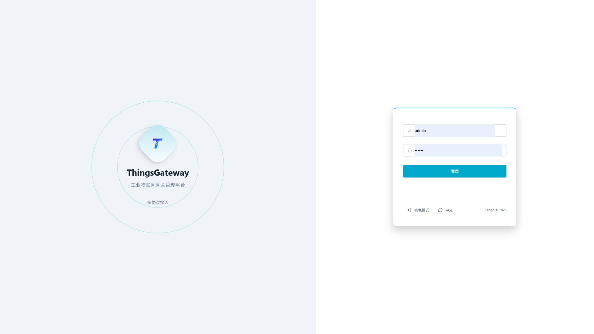
Open http://<gateway-ip>:6100, enter the username and password, and sign in to GatewayRuntime Web. The default account is admin, and the default password is 111111. Change the default password immediately after the first production login.
After logging in, you enter the "System Overview" by default. First, confirm that the page is accessible, engineering information is correct, and the number of channels and devices matches the field point list, with no persistent abnormalities in CPU, memory, or disk.
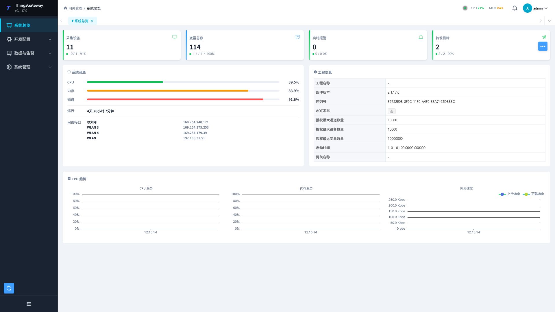
| Homepage Projects | On-site judgment method |
|---|---|
| Number of channels, equipment, and variables | Consistent with current project, point list, or delivery list. |
| Number of devices online | When creating a new link, at least the target device should be online; After commissioning, the number of offline lines should match the on-site conditions. |
| Real-time alarm | When an alarm occurs, first enter the alarm query to confirm the device, variable, alarm value, and time. |
| Checking acquisition frequency, forwarded cache, log volume, and disk space when CPU, memory, disk, | sustained high levels. |
| Project Information | Confirm whether the version, authorized quantity, gateway name, and startup time comply with the field package. |
Select Entry by Task
| On-site Task | Enter Menu | Continue Reading |
|---|---|---|
| First Confirm Whether the Gateway Is Operating Properly | System Overview | System Overview |
| Integrate PLC, Instruments, Acquisition Modules | Development Configuration → Collection Configuration | Collection Configuration |
| Verify Register Address, Data Type, or Write Point | Development Configuration → Collection Configuration → Select Device → More Functions → Debug | Plugin Manual Index |
| Configure Internal Calculation Values, State Hold or Rule Midpoint | Development Configuration → Memory Compute | Memory Compute |
| Upload data to host computer, MES, SCADA, cloud platform, or database | Development Configuration → Data Forwarding | Data Forwarding |
| Aggregate multiple edge Gateways through MQTT | Edge: Development Configuration → Data Forwarding; central: Development Configuration → Collection Configuration → Select Device | Gateway MQTT Collection Client |
| Aggregate multiple edge Gateways through one mutual-TLS port | Development Configuration → Data Forwarding | Sync Bridge |
| View current values, historical values, or trends | Data and alerts → Data query | Data query |
| Handle current alarms or retrospective historical alarms | Data and alarms → Alarm query | Alarm query |
| Troubleshoot offline, no values, forwarding failures, page errors | System logs, or collect/forward logs within the page | System logs |
| Configure network settings, time, restarts, or backups | System Management → System Settings | System Settings |
| Configure gateway takeover, recovery, or manual switching | System Management → System Settings → Gateway Failover | Gateway Redundancy |
| Modify Port, Database, JWT, and Log Retention Policies | Configuration Files | Advanced Configuration: Configuration File Description |
| External Program Call Interface | API | Development Interface: Gateway API Documentation |
Common Task Routes
Connect to a PLC or Instrument
| Sequence | Operation | Pass Standard |
|---|---|---|
| 1 | Confirm communication methods, IP/port or serial port parameters, station numbers, point tables, and byte order on site. | parameters come from equipment manuals, PLC programs, or final checklists. |
| 2 | Enter "Collection Configuration" and create a separate channel for the target device. | Channel logs show no persistent connection failures or timeouts. |
| 3 | Create a new device, select the collection plugin, and fill in plugin properties such as station number, timeout, byte order, etc. | The device shows online, and there are no persistent read/write errors in the device logs. |
| 4 | first establish 3 to 5 typical variables. | The current value matches the PLC software, instrument display, or on-site calibration values. |
| 5 | Select the device and use More Functions → Debug to verify addresses and data types. | Single-point reading is correct, then expand to the full point table. |
| 6 | Batch import or copy complete point tables. | No failure lines in the import results, and key points are spot-checked and correct. |
For detailed fields and import/export methods, see Collection Configuration. Use the Plugin Manual Index for plugin properties, variable addresses, and verification. Share a channel with another device only when the plugin manual explicitly supports it.
Verify read/write or control points
| Order | Operation | Expected result |
|---|---|---|
| 1 | and select the target device. | The right side displays the device details, channel logs, device logs, and debugging page. |
| 2 | Read read-only or safe points first. | Address, station number, data type, and byte order have been validated correctly. |
| 3 | Before writing, confirm that the field equipment allows remote control. | The device is in maintenance or allowed debugging status, and the write value is within the allowable range. |
| 4 | Write and read back feedback points. | Callback values, feedback points, or on-site status are consistent with expectations. |
Writing affects on-site equipment. For detailed debugging pages and troubleshooting, see the Plugin Manual Index.
Configure Data Upload
| Order | Operations | Confirm data scope, format, address, account, certificate, and acceptance method with the host computer, MES, SCADA, cloud platform, or database manager through Standard |
|---|---|---|
| 1 | . | The other party clearly states the Topic, URL, table name, field name, time format, and validation method. |
| 2 | First, create a small-range forwarding group with only a small number of variables. | The variable is within the group range, and the trigger method meets the other party's requirements. |
| 3 | Add a forwarding target under this group and fill in the connection parameters. | Target enabled and online, with no authentication or connection errors in the target log. |
| 4 | If an external field or Modbus slave address is needed, maintain the target variable property (the external mapping of a forwarding target to a single variable). | External system fields, addresses, or write permissions must be consistent with the protocol description. |
| 5 | Enter "Debug" or check the target log to confirm sending. | The other party can see the correct data on a specified page, Topic, table, or log. |
| 6 | Expanded to official checklist and reverted to log level. | After stable operation, log levels revert to Info. |
A variable with a value does not necessarily mean it will be forwarded. For a complete troubleshooting link, see Data Forwarding.
Data Query and Alarms
| Tasks | Operations | Notes |
|---|---|---|
| View Current Stored Values | Enter "Data Query → Real-Time Data". | Data comes from real-time data targets, not directly reread from the PLC. |
| View Historical Curves | Go to "Data Query → Historical Data". | The time range should cover the collection time, and the target must have been written to historical data. |
| Handle the current alarm | Enter "Alarm Query → Real-Time Alarm". | Confirmation of alarm only means the person is aware and does not mean the alarm condition has disappeared. |
| Export alarm records | Enter "Alarm Query → Historical Alarms." | You need to configure the historical alarm target and write the data first. |
For details on the query page, see Data Query, and for alarm handling, see Alarm Query.
Troubleshooting Faults
| Phenomena | Where to Look First | Then Look Where |
|---|---|---|
| Device Offline | Collection Configuration → Select Device → More Functions → Channel Log, Device Log | System Logs → Backend Logs |
| Variables Have No Values or Incorrect Values | Variable Address, Data Type, Byte Order, Array Length | Device Debugging Plugin references |
| Write failure | Variable read/write permissions, RPC write (external system reverse write point), write value format | Device log, RPC log |
| Data not sent | Data forwarding group range, target enabled, Trigger mode, online filtering | forwarding target logs, forwarding group logs |
| page operation failures | system logs → operation logs | backend logs |
| external system call failures | system logs → RPC Log | Equipment Log or Forwarding Target Log |
For logs usage, see System Log.
Advanced Feature Entry
| Features | Applicable Objects | Documentation |
|---|---|---|
| Rule Engine, Scripts, Custom Nodes | Engineers Familiar with Business Logic and Script Maintenance | Rule Engine, Script Management, Custom Node Types |
| Plugin Management and Manuals | Delivery Engineers, Protocol Configurators | Plugin Management, Plugin Manual Index |
| Certificate Management | Projects requiring TLS, OPC UA security policies or two-way authentication | Certificate Management |
| User, Role, Menu | System Administrator | User ManagementRole ManagementMenu Management |
| Configuration Files | On-site Administrators, Delivery Engineers, Operations Staff | Advanced Configuration: Configuration File Description |
| API | System Integration and Secondary Developers | Development Interface: Gateway API Documentation |
Frequently Asked Questions
| Phenomenon | Handling Recommendations |
|---|---|
| Login Failure | Confirm Account and Password, User Enabled, Service Port Accessibility. |
| Device Offline | First check channel parameters and device plugin properties, then check network, serial port, and device logs. |
| Variable has no value | Checks variable address, data type, device online status, and device log. |
| Write failure | Confirm read/write permissions, RPC write switch, write value format, and whether field devices allow issuance. |
| Forwarding target offline | View the forwarding target log, checking address, authentication, certificate, topic/URL/table name, and plugin status. |
| No data on the page | First confirm that the target has written data, then check the query time range, user permissions, and system logs. |