DTU Service
DTU service is used to access transparent terminals that actively connect via TCP to GatewayRuntime. GatewayRuntime serves as the TCP server's listening port. After the DTU establishes a connection, it first reports the terminal ID, and the gateway then assigns the connection to the corresponding collection device according to the DTU ID in the device. A single TCP service channel can carry multiple DTUs simultaneously without repeatedly creating listening ports for each terminal.
Applicable Scenarios
| Scenarios | Description |
|---|---|
| 4G/5G DTU Active Internet Access | Terminals located on mobile networks or on-site intranets, Terminals actively connect to GatewayRuntime deployed on public or central networks. |
| Multiple terminals share listening ports | Multiple DTUs connect to the same TCP service channel, with gateways distinguishing connections by DTU ID of each terminal. |
| Remote Transmission of Serial Port Devices | DTU transmits the serial protocols of PLCs, instruments, or acquisition modules to TCP, while GatewayRuntime continues to use collection plugins like Modbus to access field devices. |
| DDP Protocol Terminal | When the terminal explicitly supports DDP, set the channel's DTU service type to DDP. Regular registered DTUs use "default". |
Preparation Before Configuration
Before configuration, confirm the following information with the DTU manufacturer or on-site personnel.
| Information | What needs to be confirmed |
|---|---|
| Connection direction | DTU must be actively connected as a TCP client GatewayRuntime. |
| Service address | gateway IP or domain name accessible by DTU, and TCP ports that are allowed to access it. |
| Registration Identifier | DTU The terminal number, reporting timing, and encoding method reported after connection is established. |
| Identifier Format | Identify whether it is plain text or original hexadecimal bytes, and whether it contains prefixes, postscripts, line breaks, or length fields. |
| DTU Service Type | Select "Default" for the regular terminal; Only select DDP when the terminal protocol is clearly set to DDP. |
| Transparent Protocol | Protocol, station number, address, data type, byte order, and response timeout used by devices behind the DTU. |
| Survival strategy | DTU actively sends heartbeat content and cycles, as well as whether the server is required to respond to heartbeats. |
| Network Policy | Whether firewalls, port mapping, security groups, and carrier networks allow the DTU to actively connect. |
Rapid Test Configuration Generation
GatewayRuntime can generate a DTU test configuration for quickly establishing channels, devices, and variable skeleton.
- Log in to GatewayRuntime Web and go to "Development Configuration → Collection Configuration".
- Click the top right corner of the variable list to select "Show more → test data."
- Select "DTU Test Data"; it is recommended to first fill in
1for the number of devices. - "Slave Address" should be the address where the local machine or test environment can listen, for example,
127.0.0.1:15020.
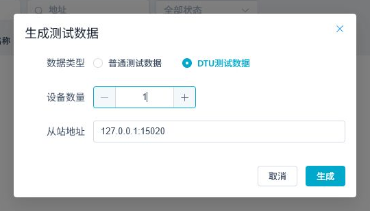
- Click "Generate". The page will create a TCP service tunnel, a Modbus collection device, a
400001variable, and a supporting test forwarding configuration. - Open the automatically generated device "Plugin Properties" and record the dynamically generated
DTU ID. - Enter the listening address and DTU ID in the real DTU or DTU/Modbus emulator, then start the terminal connection.
Successful generation only indicates that the configuration has been written. To see channels, devices, and variables online, a real DTU or protocol simulator still needs to actively connect, send a completely consistent DTU ID, and correctly respond to the collection protocol request.
Configure TCP Service Channel
Go to "Development Configuration → Collection Configuration", click "Channel Management → Add"; If you already have a channel, click "Edit".
- "Channel Name" should be filled in to represent the name of the field link, for example
dtu-modbus-service. - For "Channel Type," select
TcpService. - Enable "Enable."
- "Binding Address" is the GatewayRuntime local listening address.
0.0.0.0:15020means listening for all network cards,127.0.0.1:15020only allows local connections. - In advanced configuration, check heartbeats, maximum number of connections, client expiration time, DTU service type, and DTU ID Hex.
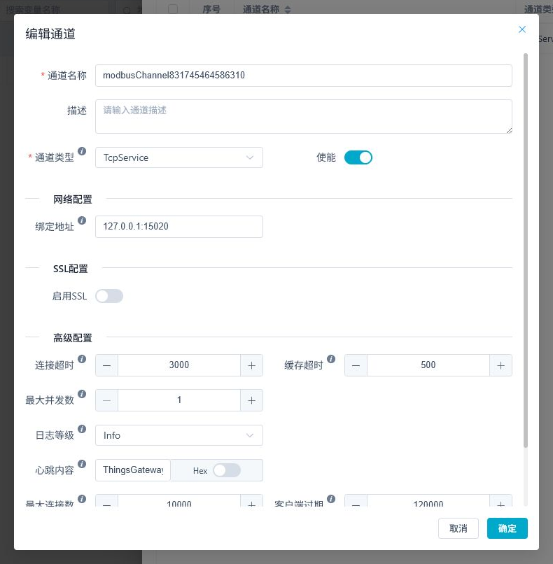
The advanced parameters for the actual verification channel DTU are as follows. The client expiration time in the screenshot is the default value of the current version 120000 ms.
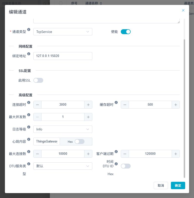
Channel Parameters
| Configuration Items | Current Default Value | Description |
|---|---|---|
| Channel Type | TcpClient | DTU Service must be changed to TcpService, the gateway waits for the terminal to proactively connect. |
| Binding address | Blank | TCP server required. For production environments, you can specify the network card address or 0.0.0.0: port. |
| Connection Timeout | 3000 ms | Timeout for establishing a connection or executing related connection operations. If the network quality is poor, the size can be increased appropriately. |
| Cache timeout | 500 ms | channel packet and protocol read cache window. Normal scenarios remain by default. |
| Maximum concurrency | 1 | Concurrent limit for requests on the same channel. On-site equipment requires strict sequential maintenance to maintain 1. |
| Heartbeat content | Empty | Filled in according to the DTU protocol. After enabling the right side of Hex, the content is parsed by hexadecimal bytes. |
| Maximum number of connections | 10000 | The number of clients the TCP service channel can maintain simultaneously. It should exceed the planned total number of DTUs connected, with room for expansion. |
| Client expiration time: | 120000 ms | If the client does not communicate within this time, communication will be disconnected. 0 means no idle clients are detected. |
| DTU Service Type | Default | Regular Registered DTU uses default mode; Only terminals that clearly support the DDP protocol choose DDP. |
| DTU ID Hex | Off | Identify terminals by text parsing when closed; When enabled, it parses as the original hexadecimal byte. |
When the DTU has a heartbeat, the client's expiration time should be significantly longer than the heart rate cycle. On site, at least 2 to 3 heart cycle cycles are usually reserved. Default 120000 ms suitable for scenarios where heart rate cycles are significantly less than 120 seconds. Setting 0 will stop free connections from cleaning up automatically and should only be used when you have a clear understanding of endpoint behavior and connection scale.
Configure DTU Collection Device
Click "Device Management → New", complete the basic information first, then enter "Plugin Properties".
- "Device Name" is the unique name of the field device or DTU.
- "Device Plugin" selects the actual transparenting protocol. This page uses
ModbusMaster. - "Associate Channels" select the previously created
TcpServicechannel. - "Execution interval" is filled in according to the on-site collection cycle, for example,
1000means one execution per second. - Open "Plugin Properties" and enter the identifier reported after terminal connection in the
DTU ID. - Continue checking the Modbus type, default station number, read/write timeout, and data parsing order.
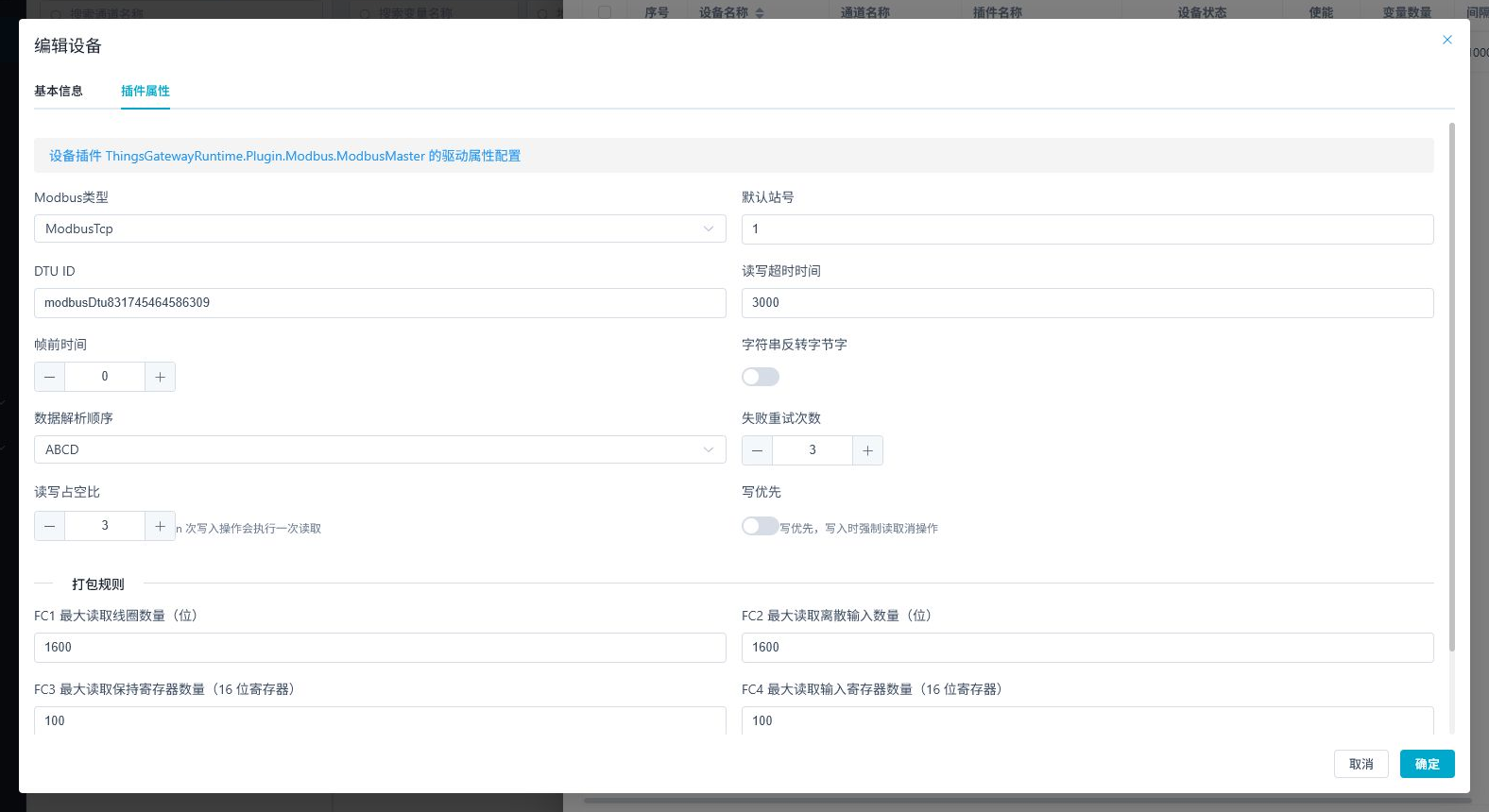
Key Device Parameters
| Configuration Items | Description |
|---|---|
| Device Plug-in | Choose the collection protocol used by real devices behind the DTU, not a universal "DTU plug-in." |
| Channel Association | Multiple DTUs can associate with the same TCP service channel. |
| Execution interval | determines the collection request cycle. If your mobile network latency is high, don't set it too low. |
| DTU ID | must be identical to the identifier in the terminal registration packet, including case and lowercase, prefix, and encoding method. |
| Default station number | slave address for protocols such as Modbus must match the device behind the DTU. |
| Read and write timeout | The waiting time for a single protocol request to respond should be set together with the mobile network latency settings. |
The "DTU ID Hex" on the channel determines how the gateway parses all access connection registration identifiers; The "DTU ID" in each device's plugin attributes determines which registered connection the device is using. When a channel carries multiple DTU, each device must fill in a different and real DTU ID.
Configure variables
Return to the main Collection Configuration workspace and click Add Variable. Verify the link with one to three typical points before importing the complete point list.
| Configuration Items | Example | Description |
|---|---|---|
| Variable Name | modbus400001 | Recommended to correspond to the on-site point table name. |
| Belonging Device | Current DTU Device | Variable must belong to the device configured with the correct DTU ID. |
| Variable Address | 400001 | Fill in according to the address rules of the collection plugin. |
| Data Type | Int16 | must match the actual data in the field register. |
| Read and write permissions | Read-only | For first-time joint debugging, it is recommended to use read-only points first. |
Text and Hex DTU ID
| Actual Message Sent by the Terminal | DTU ID Hex | DTU ID Description of the DTU ID | in the Hex Device |
|---|---|---|---|
Text DTU-001 | Close | DTU-001 | Common ASCII/UTF-8 Registration Number. |
Original byte 44 54 55 2D 30 30 31 | Enable | 4454552D303031 | After parsing the original byte, match the device with unseparated hexadecimal identifiers. |
Don't enable Hex directly just because the terminal manual displays the text number in hexadecimal. The first registration packet after the terminal establishes a connection should be captured to confirm that it is sending character D T U - 0 0 1 or the corresponding original byte sequence.
Actual Runtime Verification
After completing configuration, let the DTU actively connect to GatewayRuntime and perform acceptance in the following order.
- The left channel shows "Online," with the number of online devices at
1/1. - Devices under the channel show green online status.
- Variables no longer display "Abnormal"; current and original values can be refreshed normally.
- Collection times are continuously updated, and the reading results are consistent with field equipment, PLC software, or simulators.
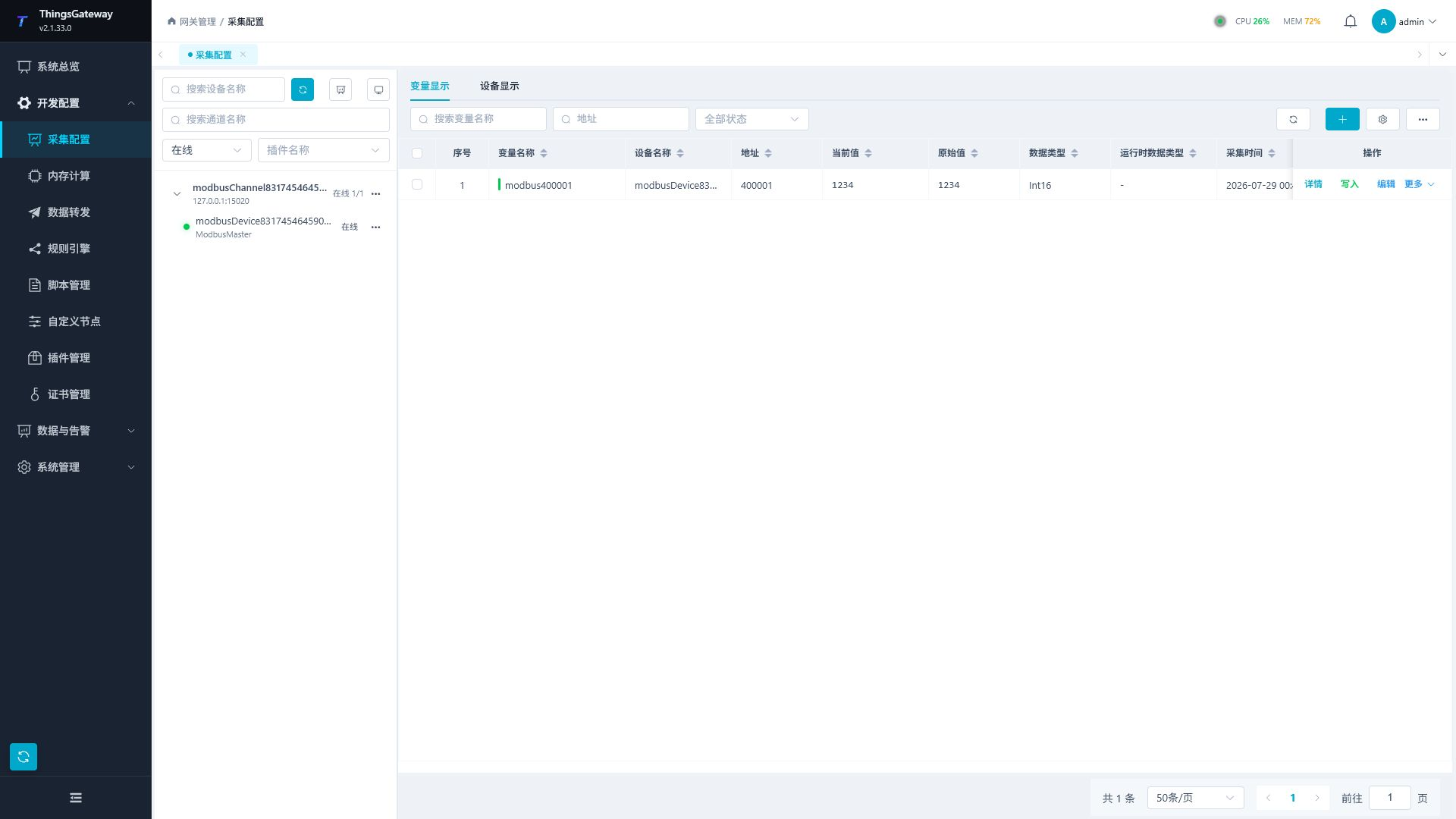
The screenshot shows where to check online state, current value, original value, and collection time. In a real project, use the field DTU ID, variable address, and device response values.
Passed Standard
| Checkitem | Listening via standard |
|---|---|
| TCP | channel is activated, and the port is in listening mode. |
| DTU registration | channel online increases, and logs show DTU connections as successful connectors. |
| Device Status | Devices using this DTU ID are displayed online. |
| Variable Quality | No abnormal markers for variables; current, original, and collection times update normally. |
| Numerical Accuracy | Reading results match the settings of field instruments, PLC software, or simulators. |
| Disconnected Recovery | After disconnecting and reconnecting the DTU, the device can resume online and continue data collection. |
Production Deployment Recommendations
| Project | Recommendations |
|---|---|
| Listening addresses | Only listening for network cards and ports required by the business; When using 0.0.0.0, it works with firewalls to limit sources. |
| Public Network Access | Confirm public IP addresses, port mappings, security groups, and operator network policies; do not directly expose unprotected management ports. |
| DTU ID | assigns a unique identifier to each terminal, and upon delivery, the DTU ID, device name, and site location are compiled into a corresponding table. |
| Heartbeat and Expiration | The heartbeat cycle must be less than the client's expiration time, with reserved time for network jitter and retransmission. |
| Maximum Number of Connections | Set according to the official number of terminals and expansion plans, avoiding connections that are too small and not expanding without boundaries. |
| Log-level | Debugging can temporarily use Debug or Traceto restore Info after stabilization. |
| TLS | Enable SSL and configure certificates when the DTU supports TLS; When not supported, use private networks, VPNs, firewalls, and source restriction protection links. |
| Write Security | The first joint debugging verifies only reads. Enable RPC pre-write confirmation for on-site interlocking, permission, and readback checks. |
Troubleshooting
| Phenomenon | Key Inspection |
|---|---|
| Channel Fails to Start | Check whether the bound address belongs to the local machine, whether the port is occupied, whether the listening port has permissions, and whether the firewall policy is correct. |
Channel shows whether 0/N | DTU is actively connected, whether the destination IP/port is correct, and whether the registration packet has been sent. |
Log prompts Client (DTU) not connected | The DTU ID in the device does not match the terminal registration identifier, or the terminal has not yet completed registration. Focus on checking text/Hex, case sensitivity, prefixes, and spaces. |
| Channel online but device offline | There may be a client connection but no valid connection matching the device's DTU ID, or protocol requests may keep timed out. |
| Device online but variable anomalies | Checkstation number, variable address, data type, Modbus type, byte order, and read/write timeout. |
| Periodic connection disconnections | Check client expiration time, DTU heart rate cycle, and heartbeat content. The heartbeat cycle should not be close to or exceed the expiration date. |
| Default mode cannot register | Confirm whether the terminal actually uses DDP; Service types are only switched when the protocol is explicitly DDP. |
| Multiple DTUs are swapped out | Check if the same DTU ID is being used repeatedly. Each terminal must use a unique identifier. |
| After reconnection, still use the old connection | Check whether the terminal sends the full DTU ID immediately after the new connection is established, and confirm the new connection is registered through the channel log. |
Related Documentation
- Collection Configuration - Complete Operation Instructions for Channels, Devices, and Variables
- Plugin Manual Index - Protocol read/write and log debugging for the selected plugin
- Data Forwarding - Forwarding the collected data to the external system