Collection Configuration
Feature Overview
Collection Configuration maintains channels, devices, and variables. It is the main GatewayRuntime entry point for connecting field devices, collecting point data, configuring alarms, and controlling writes.
When there is no ready-made collection plugin but the protocol can be described using fixed requests, framing rules, and data offsets, please refer to Custom Full Packet.
Operation Steps
- Open Development Configuration → Collection Configuration.
- Create one channel for each collection device and enter its IP, port, or serial settings. Skip the channel only for plugins that do not use a standard channel.
- Create the device, select its collection plugin, and fill in the plugin-specific properties.
- Create one to three variables, verify their values, and then import the complete point list.
- Select the device on the left, click More Functions in the device context bar, and use the Debug tab to read before writing. Export the finished configuration after verification.
For ordinary collection devices, use one channel per device. Share a channel only when the plugin manual explicitly supports it. DTU Service and Gateway MQTT are documented shared-connection exceptions.
First, look at the terminology
| Terminology | Field meaning |
|---|---|
| Channel | Gateway-to-device communication link, such as a TCP connection, a set of UDP communications, or a serial port. |
| Equipment | A PLC, instrument, acquisition module, or logic device managed by a plugin. Ordinary devices should use their own channel. |
| Variable | A point in the point list, such as temperature, pressure, operating status, fault state, or control write point. |
Other Channel Type | No standard communication channel plugins. Plugins do not require ordinary TCP, UDP, or serial channels; connections are handled by the plugins themselves or do not require external connections. |
| Cron expression | Timer expression. For routine on-site cycles, it is recommended to prioritize the number of milliseconds, for example, 1000 means 1 second. |
| RPC writes | external system or page backwrite points. Only control points need to be turned on; monitoring points are generally kept off. |
| StreamAsync | Serial port asynchronous read/write method. Maintain default when serial communication is stable; Adjust only when encountering issues such as blockages or untimely reads. |
| DtuId/DTU Number | DTU or Passthrough Terminal Number, used to distinguish which remote device is accessing. |
| Topic | Topic/path in message systems such as MQTT or Kafka, which can be understood in the field as the data channel name agreed upon by the external system. |
Function Entry
After logging into GatewayRuntime Web, click the "Development Configuration → Collection Configuration" menu on the left.
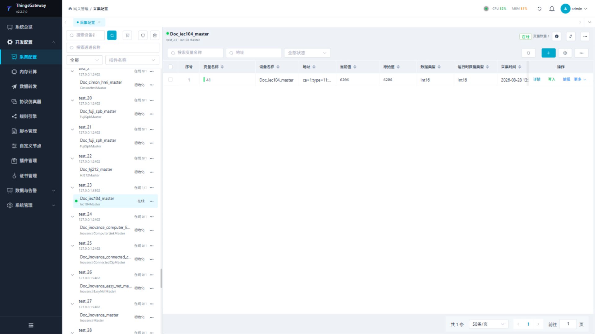
Confirm Before On-Site Configuration
There are many parameter tables on this page; do not start by field at the site. First, clearly confirm the communication link and point table boundaries, then configure them in the order of "channel, device, variable."
| What to confirm first? | Information to be received on site. |
|---|---|
| Communication methods: | TCP client, TCP server, UDP, serial port, OPC UA, OPC DA, MQTT, or plugin self-managed connections. |
| Connection Parameters | IP, port, serial number, baud rate, check bit, stop bit, account password, certificate, firewall policy. |
| Device Identity | PLC model, station number, slave station address, rack slot number, DTU number, OPC node space, or MQTT Topic. |
| Point Table | Variable name, address, data type, unit, range, read/write permissions, alarm threshold. |
| Verification Method | Use PLC software, instrument surface board, host computer page, or on-site calibration values to confirm the reading results. |
| Security Boundaries | Which points are read-only, which points are allowed to write, and who needs to confirm before writing. |
On-site Recommended Order
When connecting devices on-site, it is recommended to configure them using a "small number of validations, then batch expansion" approach. Do not import the full site table from the start, as communication parameters, station numbers, addresses, and data type issues will be mixed together, making troubleshooting costly.
| Sequence | Operation | Create a new channel through standard |
|---|---|---|
| 1 | and fill in IP, port, or serial port parameters. | Channels can connect, and channel logs do not have persistent timeouts or connection failures. |
| 2 | Create a new device, select the collection plugin, and fill in plugin properties such as station number, timeout, and byte order. | The device shows online, and there are no persistent read/write errors in the device logs. |
| 3 | first establish 3 to 5 typical variables. | The current value matches the PLC software, instrument display, or on-site calibration value. |
| 4 | Confirm data type, unit, range, read/write permissions, and alarm threshold. | The checklist matches the final on-site confirmation version. |
| 5 | Then batch import or copy the complete point table. | No failed lines in import results, and key points are spot-checked. |
| 6 | Export Collection Configuration and Archive. | The delivery package includes the final Excel configuration and point table. |
Configuration Levels
| Levels | Describes |
|---|---|
| channels | communication links, such as TCP clients, TCP servers, UDP, serial ports, etc. First, connect the passageways, then continue building the equipment. |
| Device | Collection Object, select the specific collection plugin. Most equipment needs to be assigned to the channel; Plugins that only support Other can skip the regular channel. |
| Variable | Points under the device, defining address, data type, read/write permissions, alarms, value filtering, and expressions. First, create a small number of variables for validation, then import the complete point table. |
Page Structure
| Area | Description |
|---|---|
| Left Resource Panel | Display devices grouped by channel; channel titles display the number of online devices and channel summaries; Other type devices not bound to the regular channel are displayed in tiled groups. The panel supports filtering by device name, channel name, device status, and plugin name. |
| Device Context Bar | Shows the selected device, channel, collection plugin, online state, and variable count, with actions for details, editing, and More Functions. |
| Persistent Variable Workspace | Displays variables for the selected resource. Opening details, logs, or debugging does not replace the variable list. |
| Operations Workspace | Opens from More Functions and contains Debug, Channel Log, and Device Log tabs. On desktop it can be placed below or to the right and resized by dragging the separator. |
| Page Operations | The resource panel provides refresh and channel/device management. The variable toolbar Show More menu contains import, export, and test-data commands. |
After selecting a channel or device on the left, the variable list on the right is filtered to that scope. Device rows show online status, redundancy role, and collection plugin so you can quickly confirm that each device uses the intended channel and plugin.
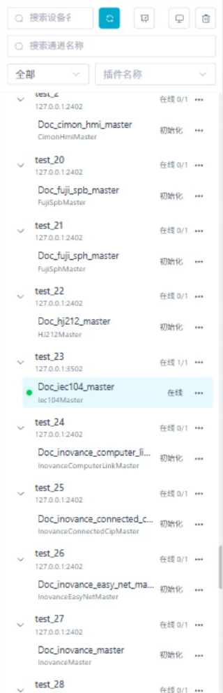
Resource Panel Operations
| Operation | Instructions |
|---|---|
| Search by device name | Filter resource panel by device name. |
| Search channel names | Filter by device channel name. |
| Device Status Filtering | Only displays online or offline devices. |
| Plugin Name Filter | Only displays devices under the specified collection plugin. |
| Select channel groups | View devices and variables under that channel. |
| Select Ungrouped Devices | View Other types of devices and variables that do not require a standard communication channel. |
| Select the device | View its variables and use the device context bar to open details, editing, or the operations workspace. |
Channel Management
Click "Channel Management" to open the Channel Management drawer.
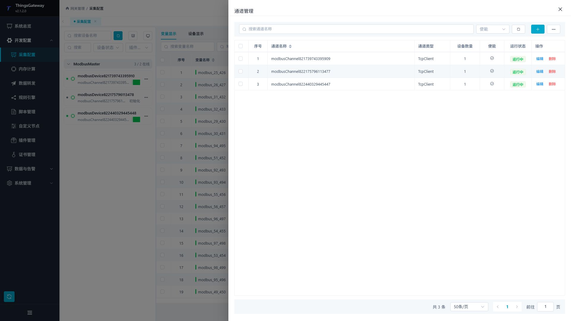
| Operations | Description |
|---|---|
| Search | Filter channels by channel name or enabled status. |
| Added | to open the channel configuration popup and create a channel. |
| Edit | Modify the basic channel information and communication parameters. |
| Delete | Delete individual channels. Before deletion, confirm that devices under the channel are no longer in use. |
| Batch Edit | Batch adjust some configurations of selected channels. |
| Batch Delete | Delete multiple selected channels. |
| Refresh | Reread the channel list. |
Channel Configuration
Click "New" or "Edit" to open the Channel Configuration popup.
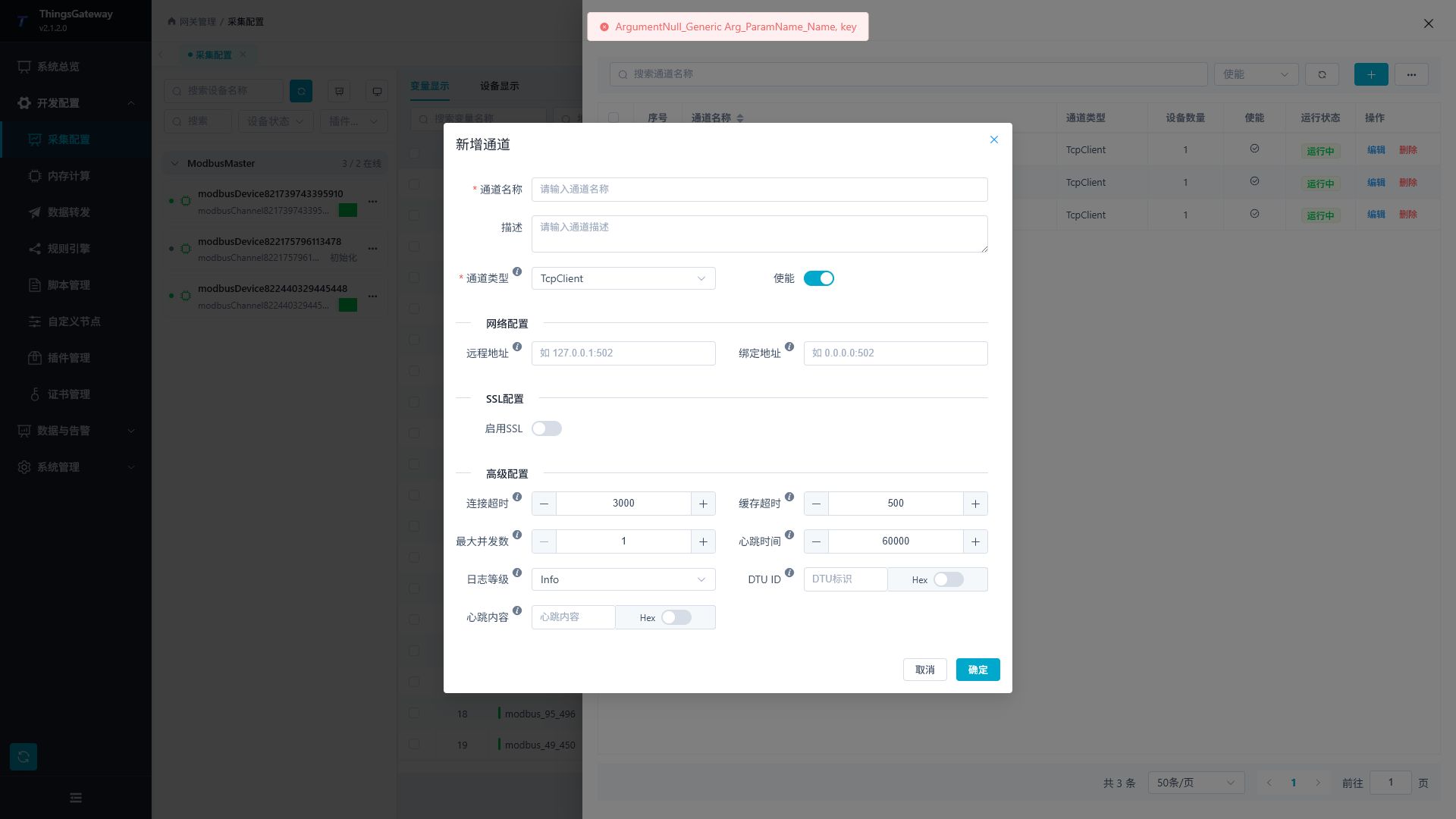
| Configuration Items | Description |
|---|---|
| Channel Name | Channel display name; it is recommended to name according to protocol, field link, or device group. Do not use Memory for names; this name is reserved for memory variables. |
| Description | Purpose of the channel, connection object, or site location description. |
| Channel Type | Select the communication method. The network channel displays the remote address, binding address, and SSL configuration; The serial port channel displays the serial port parameters. |
| Enable | to control whether the channel is running. Once closed, devices under this channel cannot collect data through this channel. |
| Remote Address | The counter address for client-mode connection, commonly in formats such as IP: port or domain name: port, for example, 192.168.1.10:502. TCP clients must provide a remote address; UDP sessions must fill in at least one of the remote address or the bound address. When providing an address with the agreement on-site, you may fill in the prefix tcp://, ssl://, or http(s):// as required by the other party. |
| Backup Remote Address | Backup peer address for TCP client channels. If the primary remote address fails to connect, the connection is disconnected, or communication times out, the channel will attempt to switch to that address within the same device and channel. As long as either primary or backup links are available, the device will not immediately switch between primary and backup devices due to a single TCP link failure. Leaving a blank means TCP client network redundancy is not enabled; The backup address should not be the same as the remote address. |
| Binding address | The address where the server mode listens locally on the gateway is commonly used. 0.0.0.0: port means other hosts are allowed to connect,127.0.0.1: port only allows local connections to be allowed. The TCP server must fill in the binding address; UDP sessions must fill in at least one of the remote address or the bound address. If protocol monitoring is required, you can fill in the tcp://0.0.0.0: Port or ssl://0.0.0.0: Port as agreed on site. |
| TLS switch using SSL | network channels. Enable when the peer requires encrypted communication, bidirectional certificates, or certificate verification; The plaintext protocol on the regular intranet remains closed. When enabling SSL on the TCP server, you must select the server certificate; otherwise, the client cannot complete the TLS handshake. |
| SSL target host | used by TCP clients to enable SSL for validation certificate hostnames. When connecting via IP but the certificate is issued to a domain name, fill in the domain name in the certificate. |
| SSL client certificate / server certificate / CA certificate | client certificate used by the gateway to prove identity to the peer; Server certificates are provided to clients when the gateway acts as a server listener; CA certificates are used to verify peer certificates. Certificates must first be maintained in the "Certificate Management" section. |
| Allows untrusted certificates | Can be temporarily enabled when debugging self-signed certificates. It is recommended to close the production environment and configure the correct CA certificate. |
| SSL protocol / check certificate revocation | specify TLS version and enable revocation check when handshake failure or on-site security policy requirements; Default is maintained without explicit requirements. |
| Port Name | The serial port name used by the serial port channel, such as COM1 or /dev/ttyS0. The serial port channel must be filled with the port name, and the host must recognize the serial port. |
| Baud rate, data bits, check bits, stop bits, | serial communication parameters must be consistent with the field equipment. |
| DTR / RTS / handshake mode | serial hardware flow control parameters. Adjust when the on-site serial server, RS485 converter, or instrument manual require activation. |
| StreamAsync | Serial port asynchronous read/write method. On-site can be understood as a serial port-driven read/write mode; When serial communication is stable, it remains at default; when issues such as blockage or untimely reads occur, adjustments can be made according to the requirements of the field driver. |
| Serial port read/write buffer | The size of the read and write buffers used for serial communication. Scenarios for large numbers of continuous or long messages can be appropriately increased. |
| Connection timeout | The maximum time a TCP connection is established or waiting for peer response. If the network is slow, the speed can be increased; If the setting is too large, offline detection will slow down. |
| Cache timeout | The validity period of the data read cache, in milliseconds. If the same address is read repeatedly during the validity period, the cache value will be returned first; It is desired to set 0 each time the device is accessed, and to reduce the repeated read pressure, it can be increased appropriately. |
| Maximum concurrency | The number of requests allowed to be processed simultaneously on the same channel. When the on-site device request order is strict, keep 1; increase after confirming that the peer supports concurrency. |
| Heartbeat Content / Heartbeat Time | Used when TCP clients maintain a connection. Fill in when the counterpart requires a fixed heartbeat message; After enabling "Is the heartbeat Hex", use hexadecimal byte parsing. |
| Maximum Number of Connections / Client Cleanup Time | TCP server channel is used to limit the number of clients and clear idle connections. If there are many upper-level computers or DTU, confirm that the maximum number of connections is sufficient. |
| DtuId/DtuId: Whether the Hex / Dtu service type | DTU or the passthrough terminal number is used to identify which remote device is connecting. The DTU reports text numbers directly when they are reported; Reporting is that when hexadecimal bytes are enabled, Hex is enabled. |
After configuring a backup remote address on the TCP client, the gateway will still prioritize connecting to the "remote address" when the gateway starts or the channel restarts. After switching to an alternate address during operation, it will retain the currently available link; Only try another link if the current link fails again. This configuration only applies to the TCP client channel on the acquisition side and does not affect the TCP server, UDP, serial port, or device primary and backup redundant configuration.
When batch editing channels, only the fields that have actually been adjusted in the batch popup will be modified. Used for unified start-stop, log levels, timeout, heartbeat, SSL, and other public configurations; The addresses, serial port names, and certificates of different types of channels should still be checked individually.
Device Management
Click "Device Management" to open the Device Management drawer.
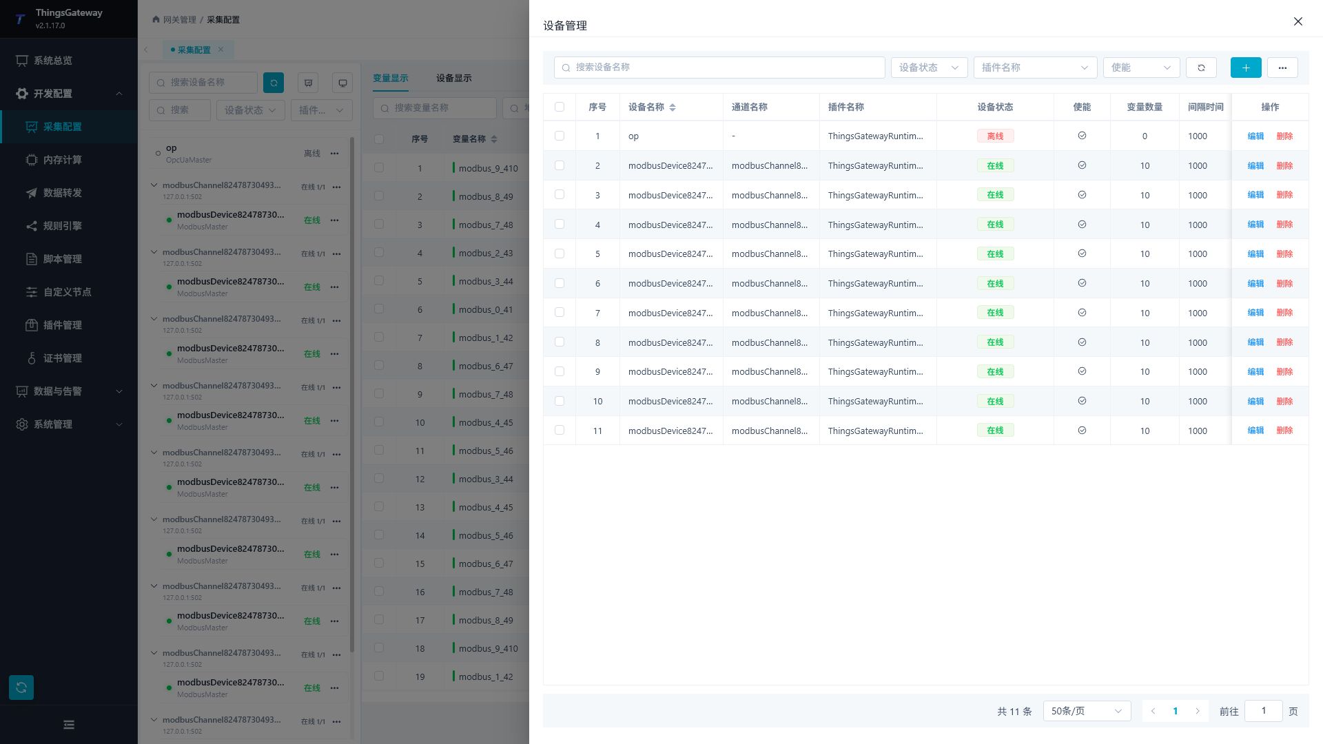
| Operation | Instructions |
|---|---|
| Search | Search by device name. |
| Status Filtering | Filter by online or offline status. |
| Plugin Filtering | Filter by Collection Plugin. |
| Enable Status Filtering | Enable or Disable Filtering. |
| Added | to open the device configuration popup and create a device. |
| Edit | Modify device base information, plugin properties, and redundancy configuration. |
| Delete | Delete the device. Before deletion, confirm that variables under the device are no longer needed. |
| Batch Edit | Batch adjust some configurations of selected devices. |
| Batch Delete | Delete multiple selected devices. |
| Refresh | Reload the device list. |
Device Configuration
Click "New" or "Edit" to open the device configuration popup.
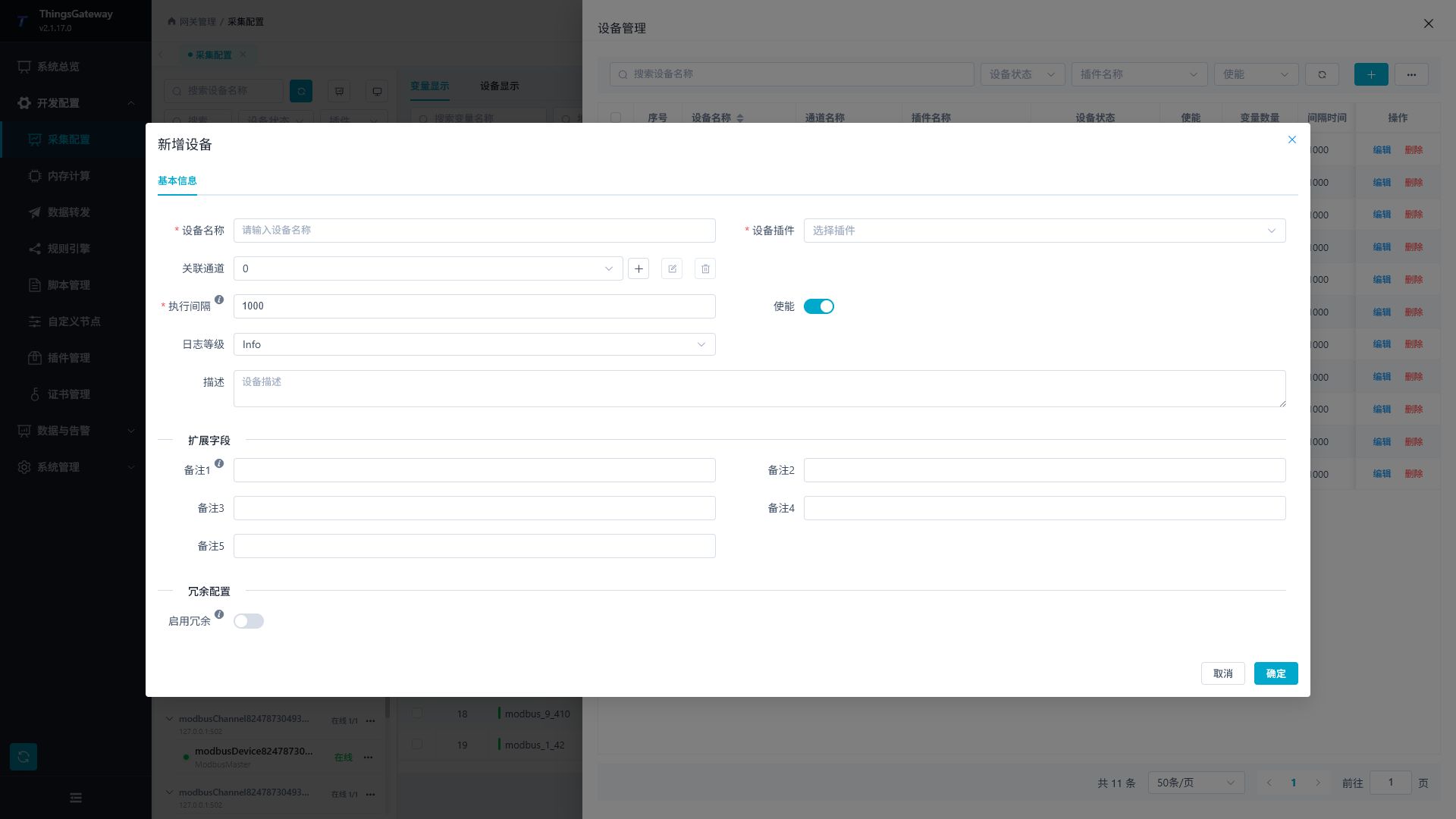
| Configuration Items | Description |
|---|---|
| Equipment Name | The device display name should match the on-site equipment number. Names should not include English periods ., do not use Memory. Memory is the device name used by the system memory variable. |
| Device Plugin | Select the Collection Plugin. After selection, the device attributes of the plugin will be displayed. |
| Channel | Select the channel used by the device. TCP, UDP, and serial plugins normally require a channel; use one channel per device unless the plugin manual explicitly documents channel sharing. Plugins that only support Other (without a standard communication channel) can be left blank. You can add, edit, or delete channels next to this field. |
| Execution interval | The device collects execution intervals, which can be filled in milliseconds or Cron timer expressions, for example, 1000 means 1 second, */5 * * * * * means every 5 seconds. Priority is given to filling in milliseconds during routine on-site cycles; The smaller the spacing, the higher the real-time performance, but it increases the load on devices and gateways. |
| Enable | to control whether the device participates in collection. |
| Log Level | Control the detail of equipment operation logs. When troubleshooting, you can temporarily upgrade the log level. |
| Description | Equipment usage, site number, or installation location. |
| Notes 1 to 5 | Custom extension fields for the project. |
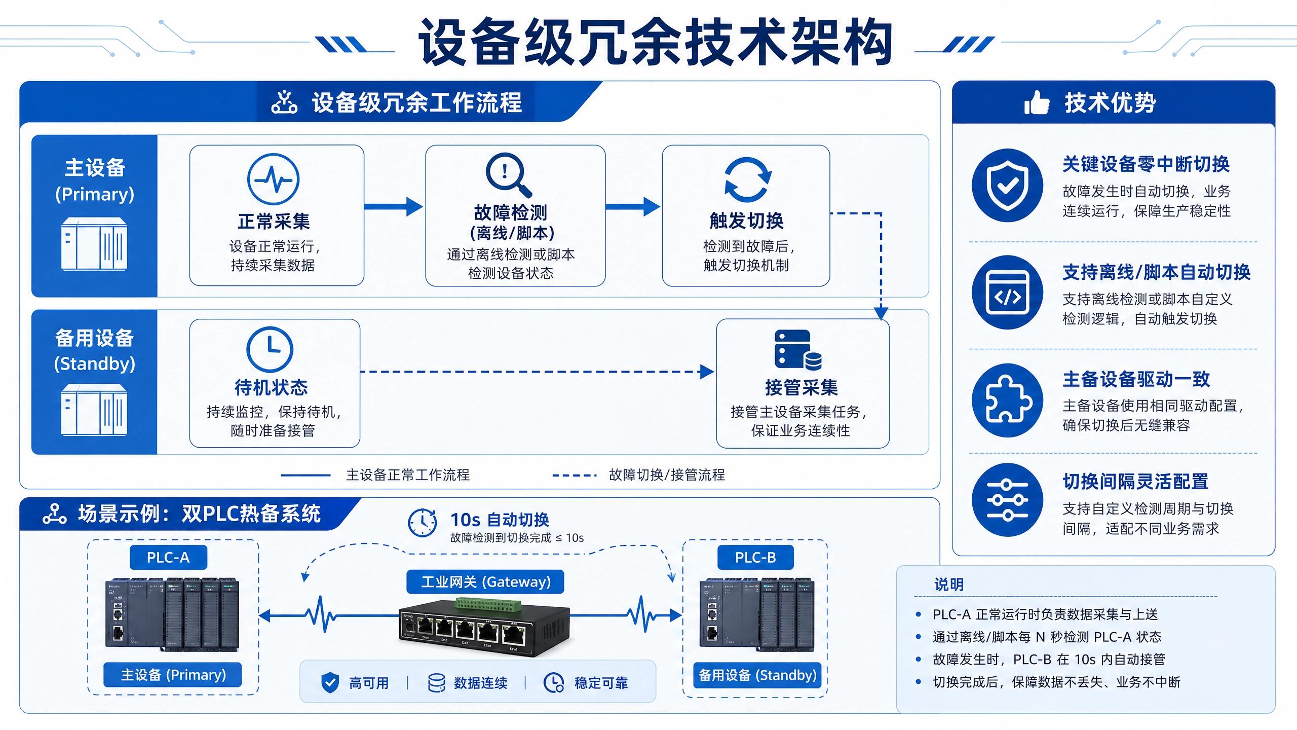
| Enable redundancy | Configure backup devices for critical equipment. |
| Redundant devices | After redundancy is enabled, select backup devices. Backup devices should use the same collection plugin and have configured channels, plugin properties, and variables; Equipment that has already been used as a backup for other devices cannot be reselected. |
| Redundancy Mode | can switch offline, or switch via scripts. Offline switching is suitable for automatic switching when the main device is inaccessible; Script switching is suitable for judgment based on quality, business status, or external conditions. |
| Scan interval | Redundancy state check interval, unit milliseconds, minimum 10,000. The shorter the interval, the faster the switching, but this increases the frequency of inspections. |
| Switching Scripts | Redundancy mode is selected when switching scripts. The script should return the decision on whether to switch, making it suitable to decide between principal and standby based on business conditions. When switching scripts, you must select the script. |
| Plugin Properties | Provided by the selected collection plugin, such as station ID, timeout, byte order, authentication, and subscription parameters. Use the matching topic in the Plugin Manual Index for dynamic properties, address formats, special methods, and verification; configure common variable fields on this page. |
Device plugins provide available channel types. When adding or editing a device, select the plugin first and then choose a matching channel. Do not reuse another device's channel unless the plugin manual explicitly says that sharing is supported. If the plugin only supports Other (no standard communication channel), the device can be saved without a channel and appears in the ungrouped area.
Redundant devices should not duplicate overlapping configurations: Do not enable redundancy for backup devices. Before going live, you can disable the main device or disconnect the main link and observe whether it switches to the backup device as expected.
Variable List
The variable list remains visible in the main Collection Configuration workspace and shows the current resource scope.
| Tools | Description |
|---|---|
| Search by variable name | Search by variable name. |
| Search address | Search by register address or protocol address. |
| Resource Range Filtering | Select variable ranges through left-side channels or devices. |
| Status Screening | Filtering by normal or abnormal status. |
| Refresh | Manually refresh the variable list. |
| Auto-Refresh | After activating, set the variable values automatically according to the page settings. |
| Add a variable | Open the variable configuration popup. |
| Batch Edit | Batch modify selected variables. |
| Batch Delete | Delete selected variables. |
| Column Settings | Customize Variable Table Display Columns. |
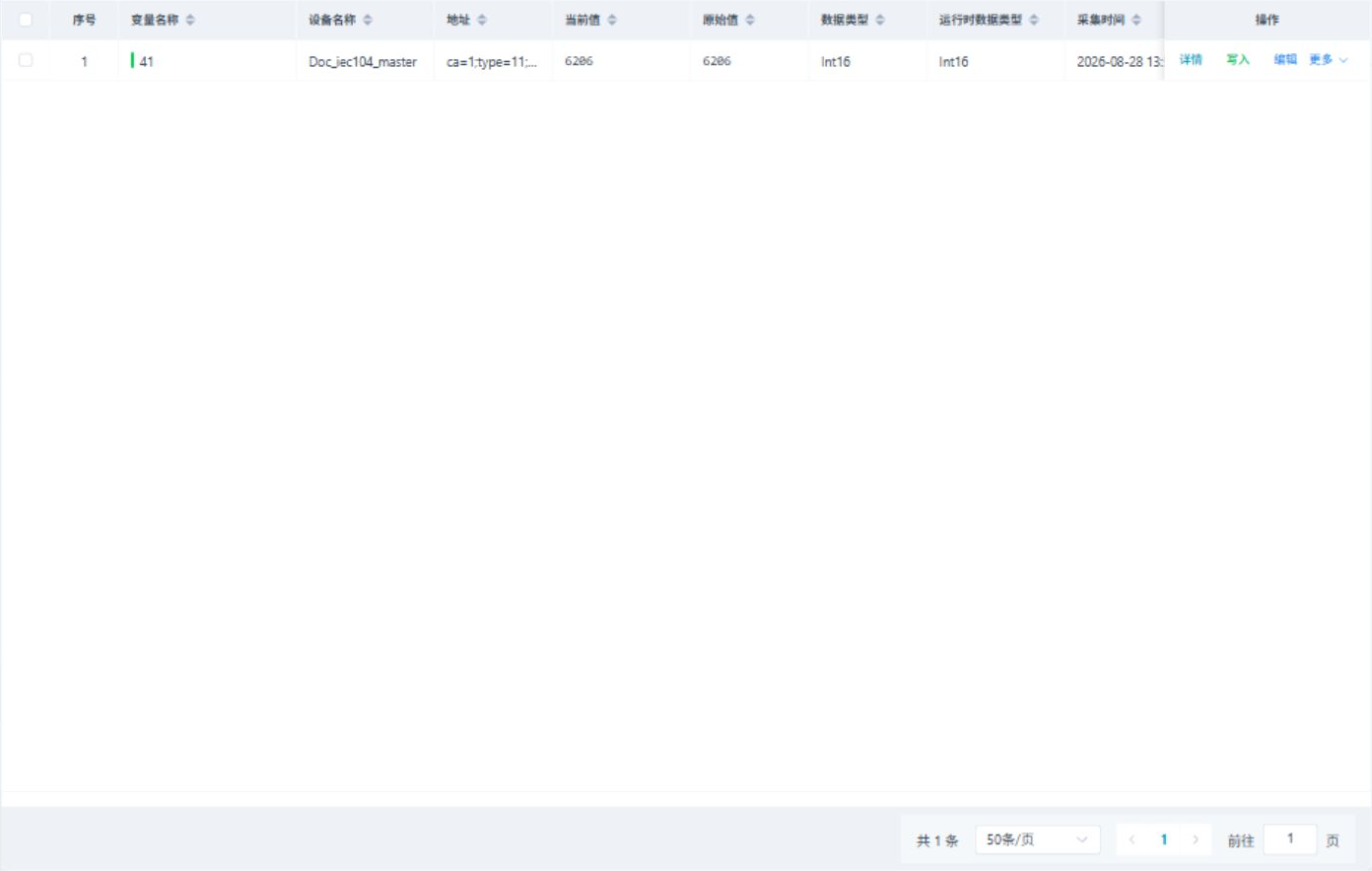
Common columns include device name, variable name, description, register address, current value, original value, last set value, data type, unit, collection group, business group, online status, enabled status, acquisition time, change time, and error information.

Memory variables are maintained on the "Memory Calculation" page. This page only displays variables under the Memory device, suitable for saving scripts, rules, or internal calculation results; The collection configuration page mainly maintains the channels, devices, and variables connected to field equipment.
Variable Configuration
Click "New" or "Edit" in the variable list to open the variable configuration popup.
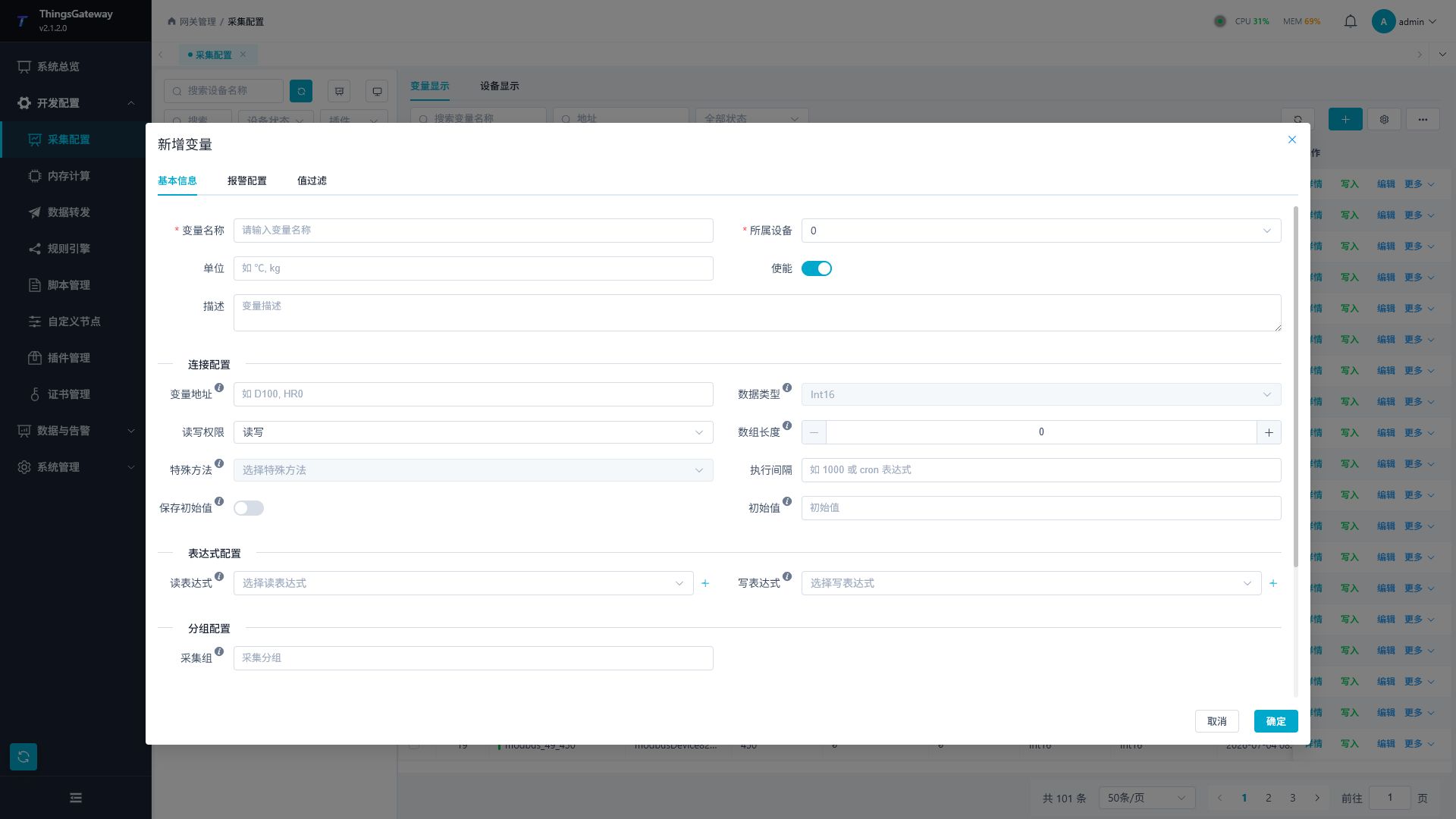
| Configuration Items | Description |
|---|---|
| Variable Name | Point Name, It is recommended to keep consistent with the device point list. |
| Belonging Equipment | Variable belonging device. After selecting a device, the address prompt and optional data types will be refreshed by the plugin. |
| Units | Variable displays units. |
| Enable | to control whether variables participate in collection. |
| Description | Description of the purpose of the location. |
| Variable address | Internal device register, node, Topic field, or protocol address. The address format is determined by plugins; for example, Modbus uses register addresses, OPC UA uses node identifiers, and MQTT uses Topic and Payload fields. |
| Data Type | Data Type of the Collected Value. It must be consistent with the actual data of the equipment; If the value display is inverted, accuracy is abnormal, or the boolean state is incorrect, the data type, variable address, array length, and plugin byte order should be checked simultaneously. Memory variables are saved by object value, without filling in the field equipment address. |
| Read and write permissions | Choose read-only, read-write, or write-only. Before writing, confirm that on-site equipment is authorized to distribute the data. |
| Array length | Length of array-type variables or batch read scenes. Ordinary point variables remain 0 or default; When reading a continuous array, fill in the actual number of elements. Memory variables do not require the array length. |
| Special Methods | Special read/write methods provided by plugins. After selection, variable addresses are usually used as parameters for this method, and are no longer packaged as regular register addresses; Only select when field protocols, plugin instructions, or debugging requirements are clearly needed. |
| Execution interval | Variable collection interval. Leave it blank or keep the default as per device interval; When independent cycles are needed, you can enter milliseconds or Cron timer expressions, such as 500 or */10 * * * * *. |
| Save Initial Value / Initial Value | After enabling saving the initial value, the variable will use the configured initial value when it starts. Suitable for memory variables, state holds, or initial states of script calculations. |
| Trigger Mode | Memory variables can be configured to trigger by variation, interval, or interval/change. Calculate the linkage according to the appropriate variation; Calculated by interval suitable cycle; The intervals/variations suit scenarios where both are needed. Ordinary collection variables perform periodic collection by device or variable, and do not require maintenance. |
| Read expressions / Write expressions | Read expressions to convert the collected raw values into business values; Write expressions are used to convert the value written to a page or external into the value required by the device. Ordinary collection variables select data conversion scripts; Read expressions for memory variables are used to calculate memory values. After selecting an expression with parameters, you need to fill in the expression parameters. |
| Read expression parameters / Write expression parameters | Input parameters required by the expression. The page displays parameter names and data types; Variables cannot be saved when required parameters are missing. |
| Collection Group | Set business group names for variables. Plugins that support packaged collection try to merge and read variables within the same group as much as possible; Data forwarding can also be filtered by collection group or in batches. |
| RPC writes | to control whether this variable allows external systems to write points backward via RPC, MQTT, OPC UA, Modbus slave stations, etc. Variables involving device control should be turned on cautiously. |
| Write Check | After a successful write, read the same variable again and compare the readback value with the write value. Suitable for points where confirmation of write is indeed effective; Devices that only write variables, have delayed effects after writing, or have proportional conversion or writeback rounding points should not be enabled arbitrarily. |
| Notes 1 to 5 | Custom extension fields for the project. |
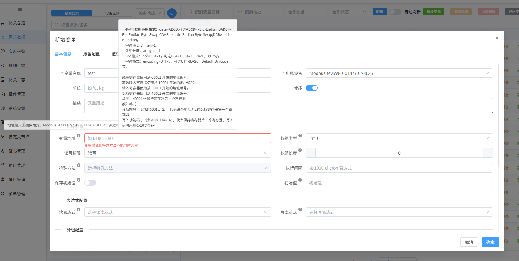
When batch editing variables, only the fields that have been modified in the batch popup are saved. Before batch modifying data types, addresses, read/write permissions, expressions, or alarms, you should first filter variables of the same device, protocol, or data type to avoid applying incompatible configurations to other locations.
Alarm Configuration
| Configuration Items | Description |
|---|---|
| Boolean Alarm / Boolean Off-Alert | Boolean variable can be configured to enable and disable status alarms separately. Alarm activation is used when the value is true, and off alarm is used when the value is false. |
| High, high, low, low-low alarms | Numerical variables can be configured with upper and lower limit alarms. When enabling multiple limits, the threshold should meet "High High > High > Low > Low Low"; otherwise, an error will appear when saved. |
| Custom alarms | Alerts configured with custom conditions. Suitable for alarms such as equipment status codes, quality codes, and combination conditions, where only upper and lower limits can be described. |
| Alarm code / alarm text | Alarm code is used to distinguish alarm types; the alarm text is the explanation seen by the duty personnel. It is recommended to clearly state the target, conditions, and direction of handling. |
| Alarm Level | Alarm severity, ranging from 0 to 10, with higher values indicating more severity. |
| Alarm Delay | Triggered only after the alarm condition has been continuously reached for a set time, in milliseconds. Used to filter transient shaking; Setting it to 0 means the alarm will sound immediately once the condition is met. |
| Suppression Expression | Suppression of corresponding alarms when conditions are met, suitable for maintenance, interlocking, or scenarios where alarms are temporarily omitted under specific working conditions. The suppression expression only affects alarm triggers and does not change the variable acquisition value. |
Value Filtering
| Configuration Items | Description |
|---|---|
| Range Filtering | Filtering outliers by minimum and maximum values. Suitable for scenarios such as occasional sensor out-of-bounds and extreme wire disconnections. After activation, you must fill in the minimum and maximum values, and ensure the maximum value is not less than the minimum. |
| Amplitude Filtering | Filter mutation values based on maximum amplitude or percentage change. Suitable for analog quantities such as temperature, pressure, and flow rate that should not fluctuate dramatically instantly. The maximum percentage change is filled in from 0 to 100. |
| Continuous Filtering | Handles duplicates or abnormal consecutive values based on the number of consecutive anomalies. Suitable for scenarios where you need to wait for the anomaly to persist multiple times before accepting or discarding it. Start from 1 in the maximum number of consecutive attempts. |
Value filtering is only used for numeric variables; Strings and boolean variables do not display this tab. If the filtering parameters are set too tightly, true changes will be filtered out. Before setting, confirm based on the field range, sampling cycle, and allowable fluctuation range.
Variable Details and Writing
Click "Details" in the variable row to open the variable details drawer.
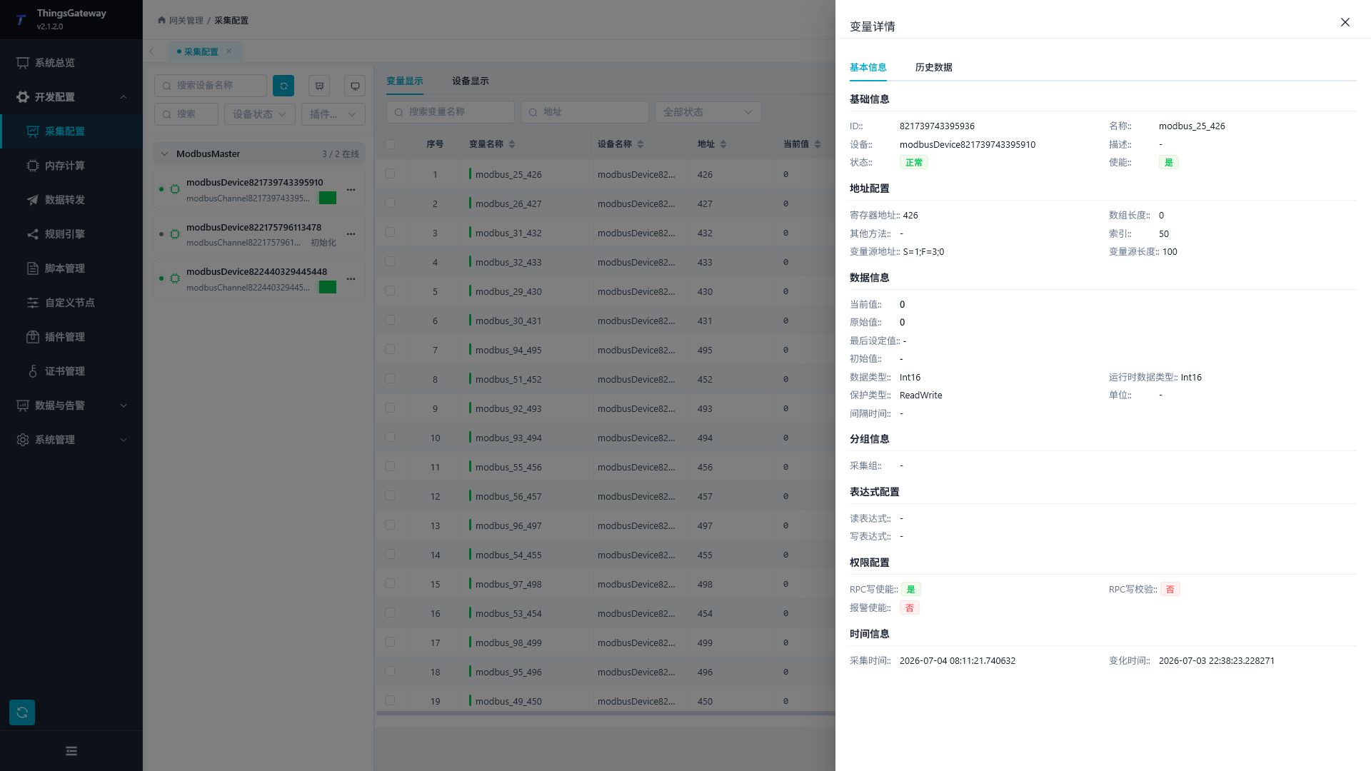
| Partition | Description |
|---|---|
| Basic Information | Displays variable ID, name, device, description, status, and enabled status. |
| Address Configuration | Displays register addresses, array lengths, special methods, and source information. |
| Data Information | Displays current value, original value, last set value, data type, unit, and interval. |
| Expression Configuration | Displays read/write expressions and parameters. |
| Alarm Information | Variable Alarm Display the alarm configuration and runtime alarm status after alarm activation is enabled. |
| Value filtering | variable is configured to display filtering parameters during value filtering. |
| Historical Data / Historical Alarms | Query the history of the current variable in the Details drawer; Historical alarms are displayed when variable alarms are enabled. |
Click "Write" in the variable row to open the write popup.
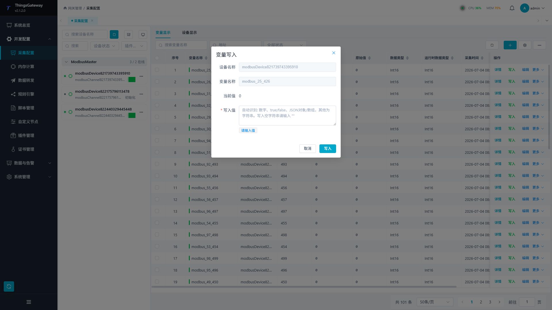
| Configuration Item | Description |
|---|---|
| Device Name | The device to which the current variable belongs, displayed read-only. |
| Variable Name | Current Write Variable, read-only display. |
| Current value | Write the variable value read from the previous page. |
| Write Value | The value to be sent, formatted to match the variable data type. |
Writing variables will affect on-site equipment. Before performing writes, please confirm the variable read/write permissions, write value ranges, and on-site security conditions.
Device Details and Debugging
Select a device on the left. Use the information icon in the device context bar to open the details drawer. Click More Functions to display the operations workspace; it opens on Debug by default.
| Entry or Tab | Description |
|---|---|
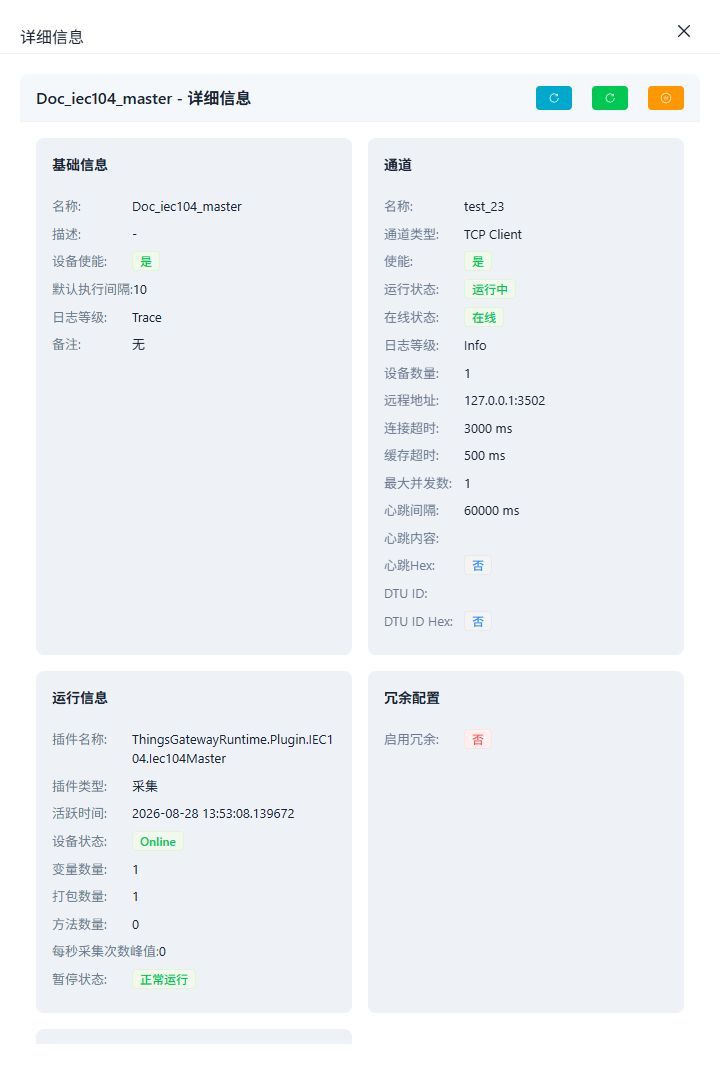
| Device Details | View basic device information, channel configuration, runtime state, plugin properties, and redundancy configuration. |
| Debug | Open plugin tools such as address read/write, node browsing, message capture, or protocol-specific diagnostics. |
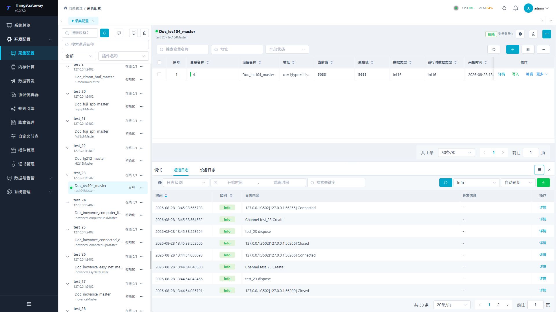
| Channel Logs | View the communication logs of the channel to which the device belongs. |
| Device Logs | View the current device operation logs and error messages. |
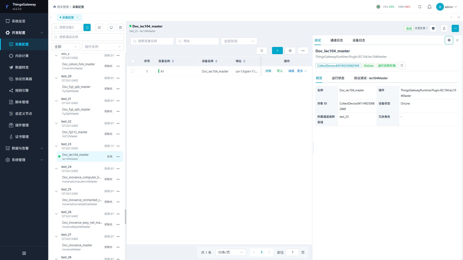
| Workspace Layout | Select Bottom or Right. Drag the horizontal separator to change height, or the vertical separator to change width. |
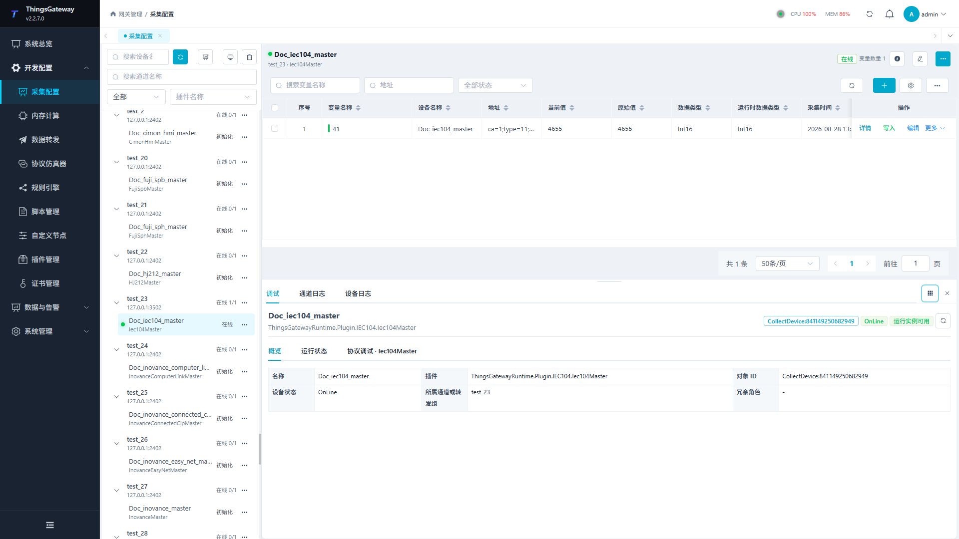
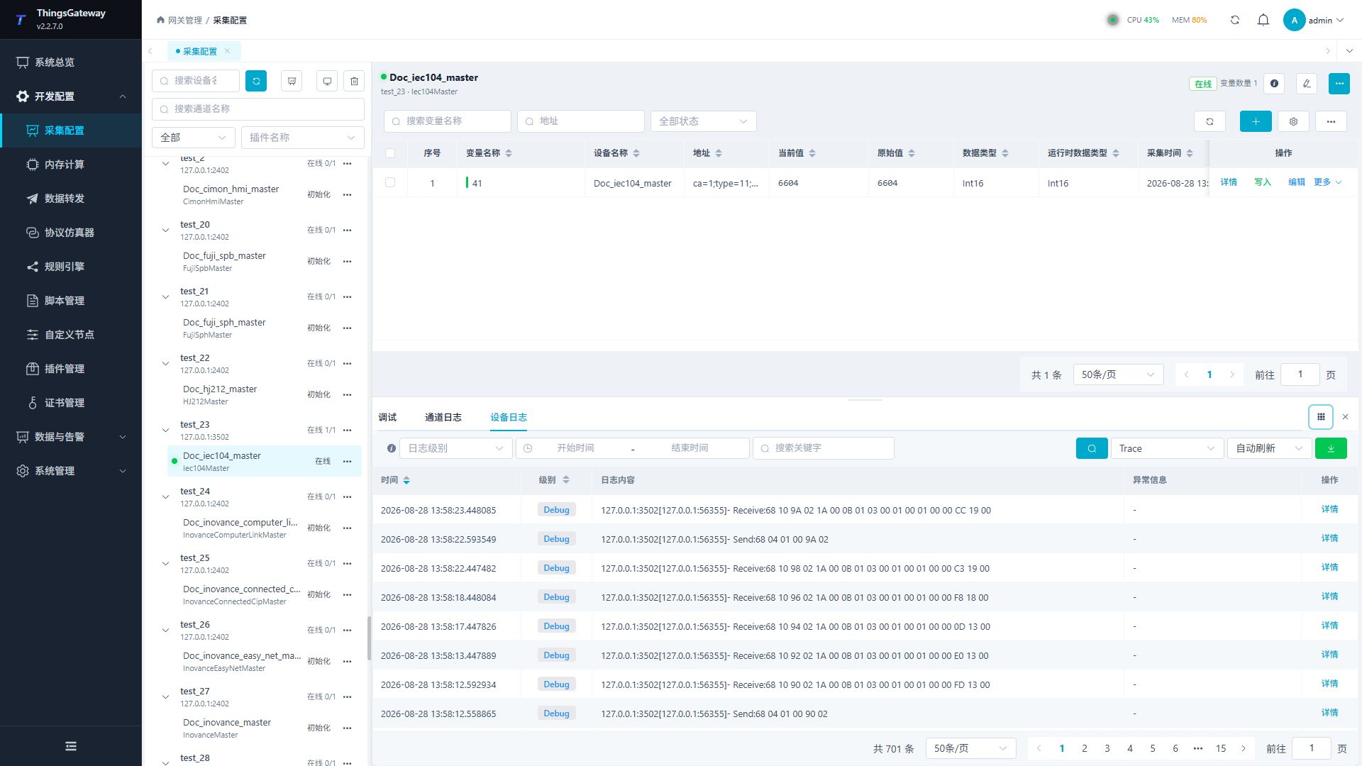
The image above only locates the common Debug entry. It is not a plugin-specific debug screen; the available tabs and operations depend on the selected plugin and are described in its manual.
When sufficient horizontal space is available, use the layout button and select Right to keep variables and diagnostics side by side.
Channel and device logs retain filtering, automatic refresh, export, and pagination inside the workspace.
When a plugin provides a protocol panel, select Protocol Debug and then use the tabs on that protocol page. The following example shows an IEC104 master.
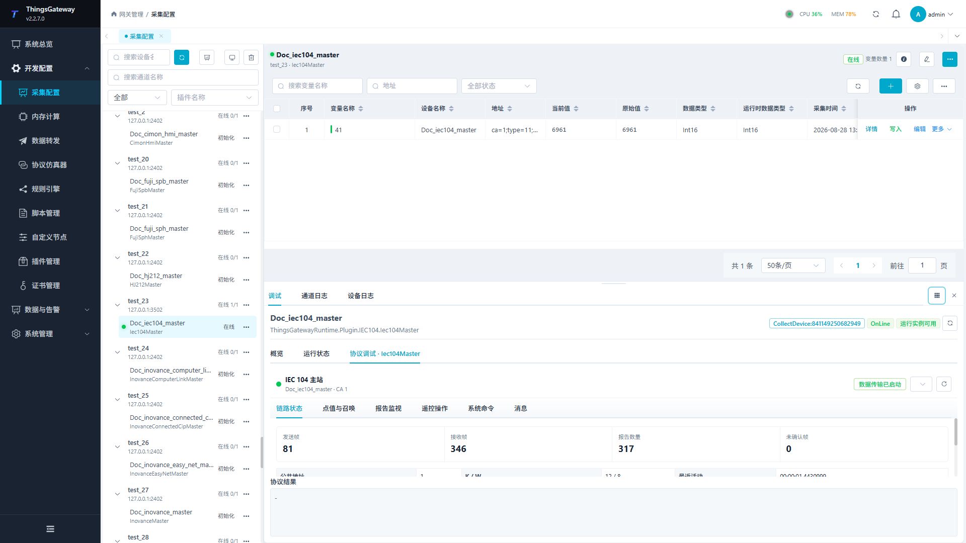
Switching devices immediately closes the previous debug panel and message-capture connection. Start message capture again from the new device when required.
For detailed debugging steps, open the matching page in the Plugin Manual Index.
Test Data
Click "Show more → test data" to open the test data generation popup. This feature is used to generate demo or stress test configurations.
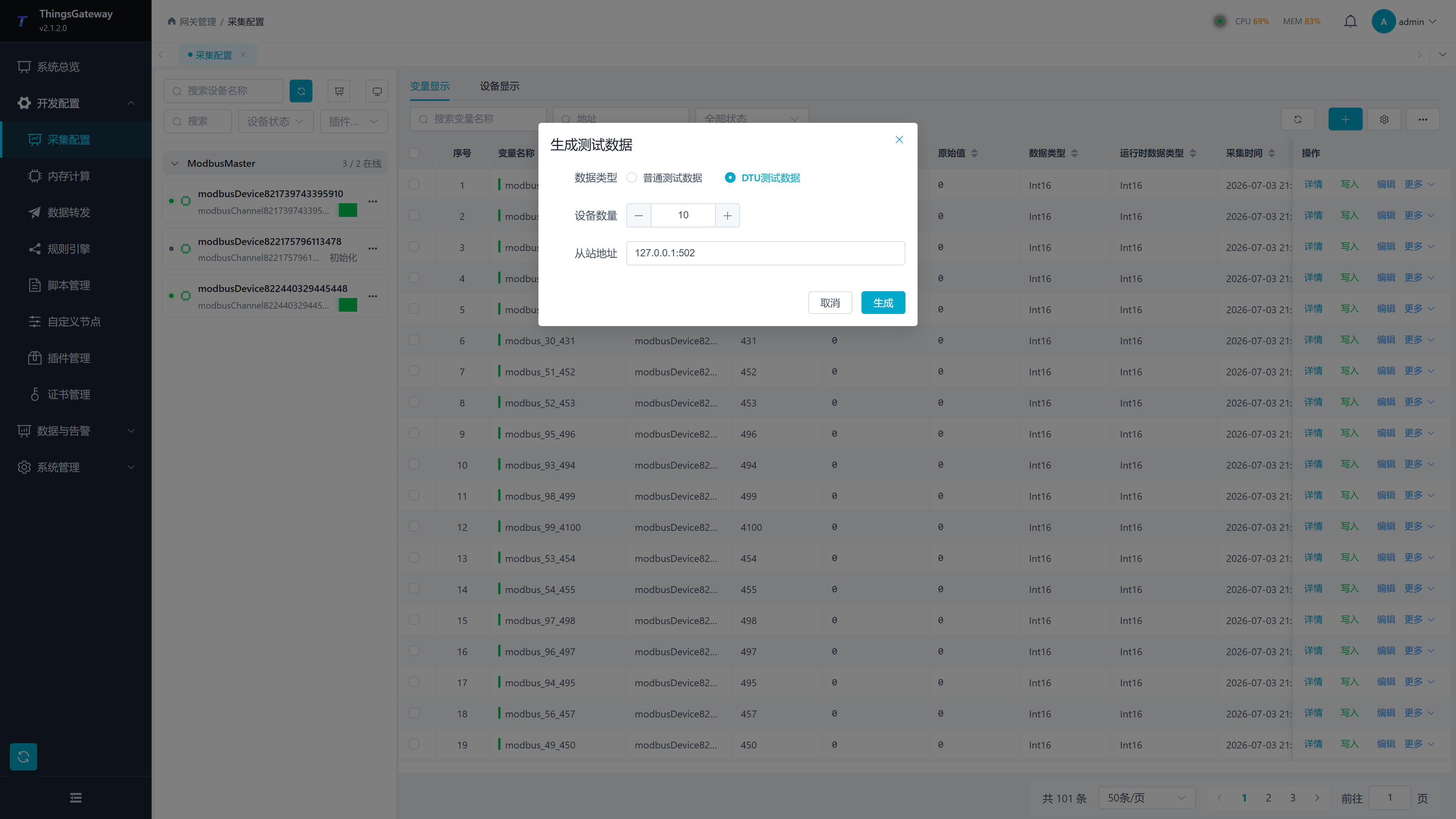
| Configuration Items | Description |
|---|---|
| Data Type | Select Normal Test Data or DTU Test Data. |
| Number of variables | Number of variables generated under standard test data. |
| Number of devices | Number of test devices to be generated. |
| Slave Address | Slave address or connection information used when generating the device. |
| Enable data forwarding | Configure whether data forwarding is generated synchronously under normal test data. |
| Generate | Generate test configurations based on the quantity and options entered in the pop-up. |
Normal test data creates a separate collection channel for each test device, which is useful for checking multiple devices and connections. DTU test data uses one TCP service channel for multiple DTUs; that is a DTU-specific shared-connection mode, not the default for ordinary collection devices.
Before using test data in production environments, it should be confirmed that the name and quantity are not confused with the official configuration.
Import and Export
Collect Configuration Import and Export is located in the "Show More" menu at the top right of the variable list.
| Operation | Description |
|---|---|
| Import Collection Configuration | Import channel, device, and variable configuration. |
| Export the current collection configuration | Export by page filter criteria and resource range. |
| Export all collection configurations | Export all collection configurations. |
After importing is complete, the import result will be displayed. When importing on site, focus on checking the failed rows, field names, and error details, then correct the Excel prompts and re-import.
Validation Results
After configuration, verify the following:
- The channel and device are online, without persistent connection or read/write errors in their logs.
- Selecting the device displays its variables, and the values, addresses, and data types match the field point list.
- A representative read from More Functions → Debug matches the variable list and field device.
- Channel Log and Device Log filtering, automatic refresh, and pagination are available.
Use Notes
| Scenarios | Recommendations |
|---|---|
| Create a new collection link | Build channels first, then equipment, and finally variables. |
| Device offline | Check channel parameters, device plugin properties, and network or serial connections. |
| Variable anomalies | Check variable addresses, data types, device online status, and device logs. |
| Batch import | First import validation in the test environment, then import into the production environment. |
| Delete channels or devices | First confirm that lower-level devices, variables, and data forwarding configurations are no longer in use. |
Related Links
- System Overview - System Status Monitoring
- Real-Time Alarm - Alarm Monitoring and Handling
- Data Forwarding - Data Collection Forwarding Configuration
- Plugin Manual Index - Per-plugin properties, addresses, special methods, debugging, and troubleshooting