Modbus Master
Purpose
The Modbus Master plugin reads and writes Modbus TCP, RTU, and ASCII devices.
Open the plugin
Open Development Configuration → Collection Configuration, create a device, and select Modbus Master as the collection plugin.
Create the channel and device through Collection Configuration. This page lists only Modbus-specific settings, addresses, and debug actions.
Supported channels and data types
| Channel type | Check before configuration |
|---|---|
| TCP client | Confirm the device IP, port, and network reachability from the gateway. |
| TCP server | Confirm the local listening address and port, and that the field device can connect to the gateway. |
| Serial port | Confirm that the port is not in use and that baud rate, data bits, stop bits, and parity match the device. |
| UDP | Confirm the bind address, port, firewall rules, and packet source. |
Supported data types: Boolean, Byte, Int16, UInt16, Int32, UInt32, Int64, UInt64, Float, Double, String, and Decimal.
Plugin properties
Modbus Master also inherits the common collection properties. Channel type, remote/local address, serial settings, TLS, connection timeout, retry count, read/write duty cycle, write priority, data format, string byte reversal, and maximum concurrency remain available in the device editor; see Collection Configuration for those shared fields and their channel dependencies. The tables below list Modbus-specific settings.
Protocol
| Setting | Description |
|---|---|
| Modbus type | Select ModbusTcp, ModbusRtu, or ModbusAscii to match the field device and channel. |
| Default station | Station used when the variable address does not specify one. The default is 1. |
Request packing
These limits control how many points are placed in one request. Keep the defaults unless the device manual specifies a smaller limit.
| Setting | Range / default | Description |
|---|---|---|
| FC1 maximum coils | 1–2000, default 1600 | Maximum coil bits read in one FC1 request. |
| FC2 maximum discrete inputs | 1–2000, default 1600 | Maximum discrete-input bits read in one FC2 request. |
| FC3 maximum holding registers | 1–125, default 100 | Maximum holding registers read in one FC3 request. |
| FC4 maximum input registers | 1–125, default 100 | Maximum input registers read in one FC4 request. |
| FC15 maximum multiple-coil write | 1–1968, default 1968 | Maximum coil bits written in one FC15 request. |
| FC16 maximum multiple-register write | 1–123, default 123 | Maximum registers written in one FC16 request. |
DTU connection
| Setting | Description |
|---|---|
| DTU ID | Identifier used to match a registered DTU connection when the channel is a DTU service. Leave it empty for ordinary direct connections. |
When the channel type is a DTU service, DTU ID must exactly match the identifier registered in DTU Service. Leave it empty for direct TCP, serial, or UDP channels.
Address rules
Use the address area that matches the Modbus function:
| Address range | Area |
|---|---|
00001 onward | Coils |
10001 onward | Discrete inputs |
30001 onward | Input registers |
40001 onward | Holding registers |
Examples:
40001is the first holding register.40001;s=2;reads station2instead of the default station.40001;w=16;uses function code16when writing the value.F=3;100explicitly uses function code3at protocol offset100for a holding-register read. WithF=, the address is a zero-based offset rather than a40001-style area address.- Combine options with semicolons, for example
S=2;F=3;100. The options apply to this variable address only.
W= accepts a positive write function code; 15 (multiple coils) and 16 (multiple registers) are the usual values. When it is omitted, the write function follows the variable data type and protocol defaults.
Use the address together with the common variable settings in Collection Configuration. Verify the address against the device point list before importing many variables.
Functions
| Function | Purpose |
|---|---|
| Read and write | Read a confirmed point and write only to an approved test point. |
| Messages | View sent and received frames, protocol fields, and error details. |
Device debug
Open Development Configuration → Collection Configuration, select the Modbus device, and click More Functions, then open Debug.
Read and write
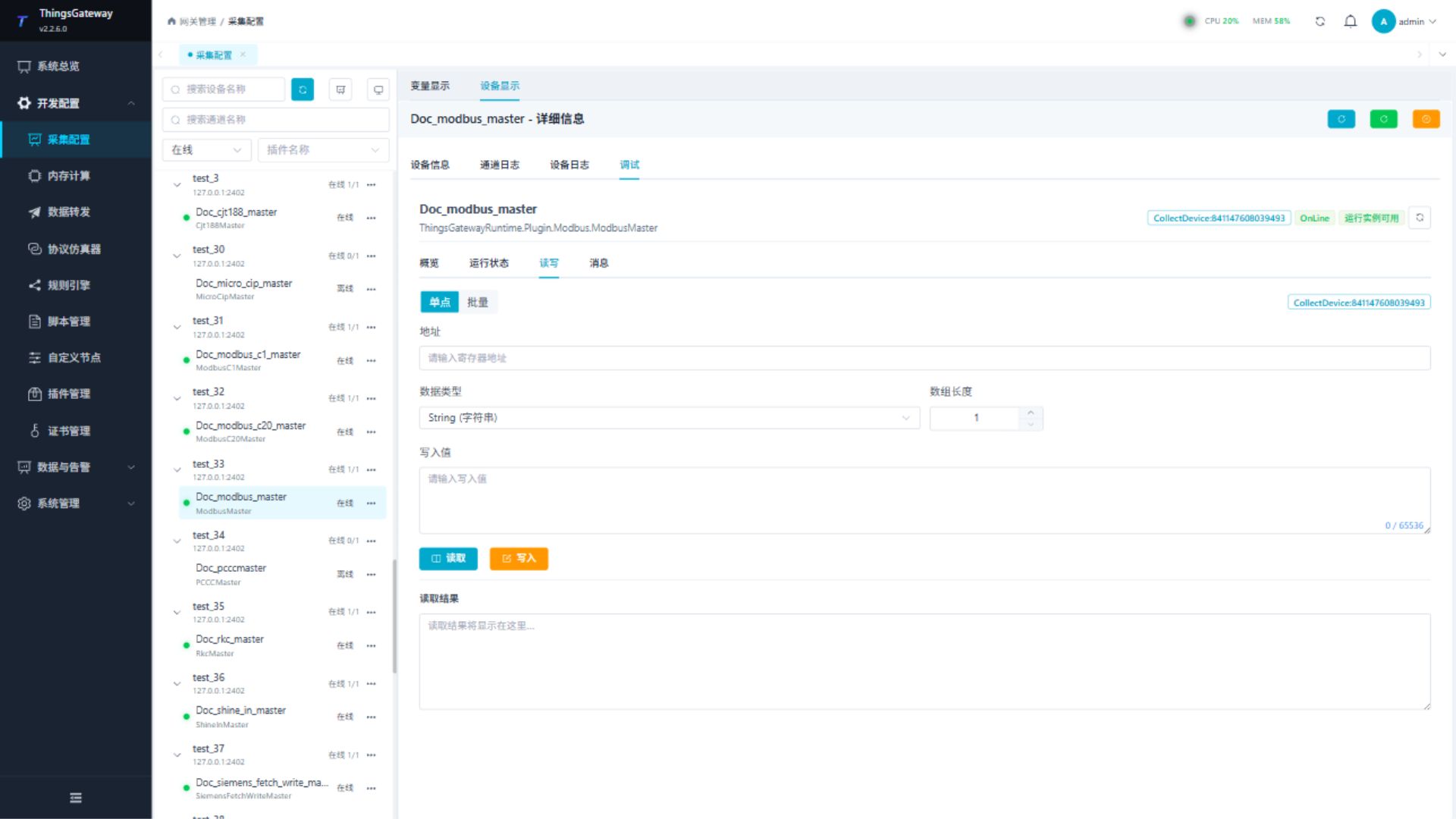
Read a confirmed safe address first. Before writing, confirm the variable permission, station, function code, data type, and field safety conditions.
Messages
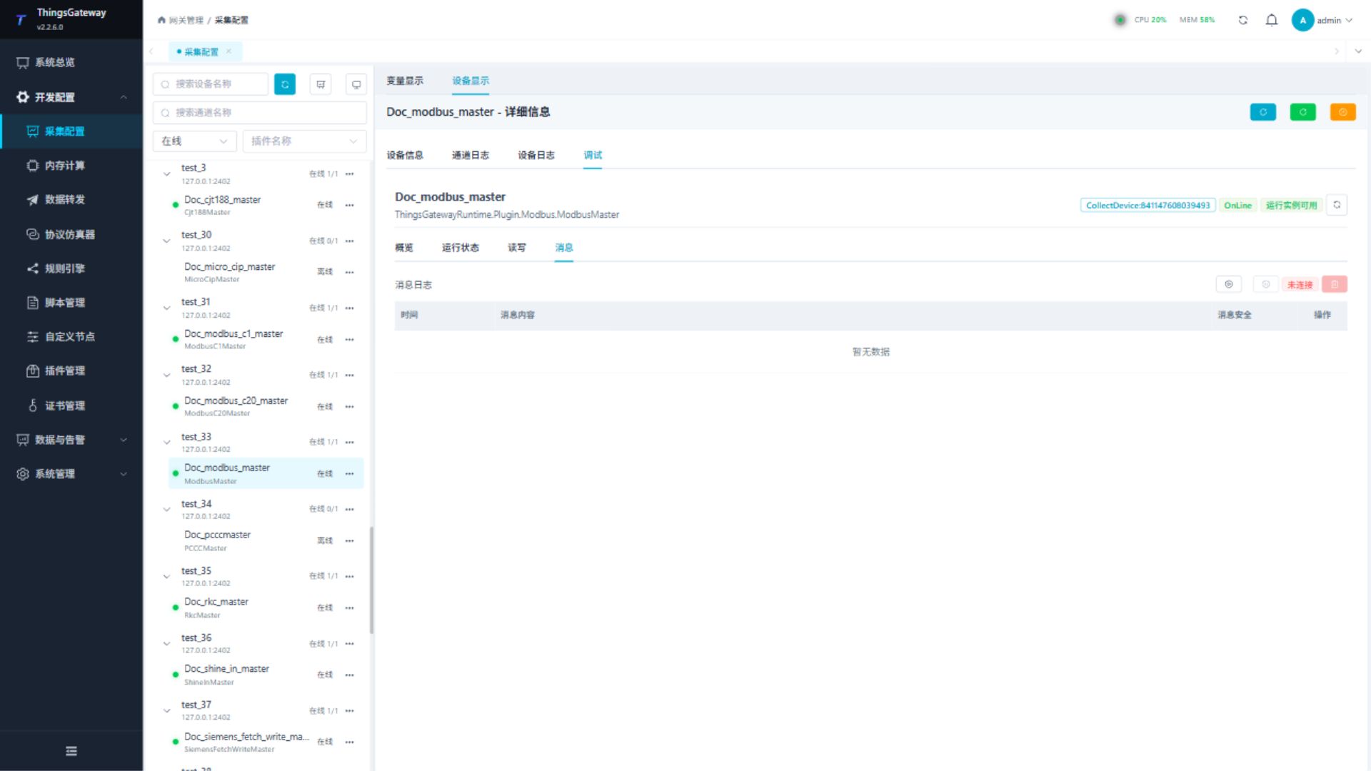
Use the message view to check sent and received frames, connection failures, and protocol parsing errors.
Verify the configuration
- Read one confirmed field address.
- Confirm that the returned value, data type, byte order, station, and function code match the point list.
- For a writable point, write a safe value and read it back according to the field procedure.
- Only after the single-point check passes should you import the complete point list.
Troubleshooting
| Symptom | Check |
|---|---|
| Address read fails | Check the address area, station suffix, data type, and device point list. |
| Serial device does not respond | Check port ownership, baud rate, data bits, stop bits, parity, and channel type. |
| TCP device does not respond | Check the remote or bind address, firewall, station, and Modbus type. |
| Values are shifted or incorrect | Check data type, byte order, array length, and the address offset. |
| Batch read is rejected | Reduce the corresponding FC1–FC4 limit and compare it with the device manual. |
| Batch write is rejected | Keep FC15 between 1–1968 and FC16 between 1–123, then compare the configured limit with the device manual. |
Related links
- Collection Configuration: Channels, devices, variables, import, and common debug entry.
- Plugin Manual Index: Other collection and data-forwarding plugins.