A3CMaster
Purpose
Mitsubishi A3C serial protocol address read and write, status and control driver
Open the plugin
Enter "Development Configuration → Collection Configuration", create a device and select "A3CMaster" in "Collection Plugin".
Supported channels and data types
| Channel type | Pre-configuration check |
|---|---|
| Serial Port | Confirm that the serial port is not occupied by other programs and maintains the same baud rate, data bits, stop bits and parity bits as the device. |
| TCP Client | Confirm network reachability of the device IP, port, and gateway to the device. |
| TCP server | Confirm that the local listening address and port are available, and allow on-site devices to actively connect to the gateway. |
Optional data types: Boolean, Byte, Int16, UInt16, Int32, UInt32, Int64, UInt64, Float, Double, String, Decimal
Plugin properties
Protocol parameters
| Setting | Description |
|---|---|
| Default station number | Default: 0; fill in: text input. Set the default station number used when the station number is not specified separately in the variable address. |
| Enable and verify | Default: Yes; fill in: switch. Controls whether the "Enable and Verify" feature is enabled. |
Data format
| Setting | Description |
|---|---|
| A3C frame format | Default: 1; fill in: drop-down selection. Set the A3C frame format used for data parsing or serialization. |
Address rules
- A3C bit device area: X, Y, M, S, L, F, V, B, SM, SB, DX, DY, TS, TC, SS, SC, CS, CC.
- A3C WORD device area: D, SD, W, SW, R, Z, ZR, TN, SN, CN.
- The default station number can be overridden for a single address using s=2;D100; WORD area Boolean access must explicitly specify a .0 to .15 bit number.
Special methods
| Method | Purpose | Parameters |
|---|---|---|
| RemoteRunAsync | Run PLC | No parameters |
| RemoteStopAsync | Stop PLC | No parameters |
| ReadPlcTypeAsync | Read PLC model | No parameters |
Functions
| Function | Purpose |
|---|---|
| Read PLC model | Use Read PLC model to inspect mapped values, status, counters, recent messages, or the latest result. |
| Remote run | Use Remote run with an approved test point and confirm site safety before execution. |
| Remote stop | Use Remote stop with an approved test point and confirm site safety before execution. |
Device debug
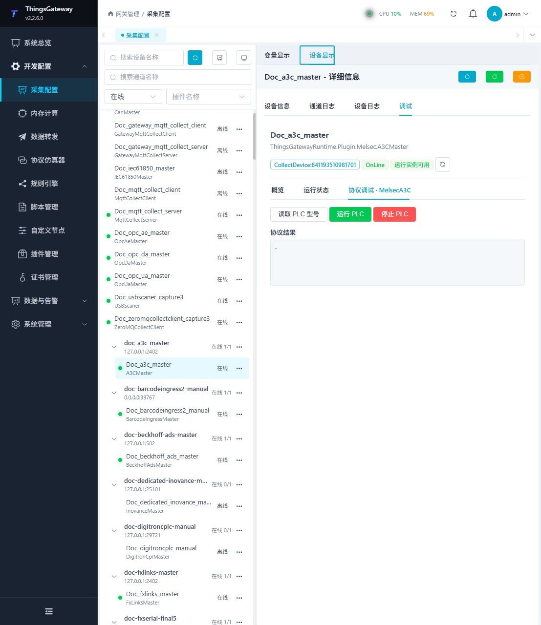
Enter "Development Configuration → Collection Configuration", select the current device and click "More Functions", then open "Debug".
Dedicated debugging page
Open Development Configuration → Collection Configuration, select the device, and open More Functions → Debug. The following image shows the plugin-specific debug page.
Debugging notes
Read the PLC type first; remote running and stopping are high-risk controls and must be confirmed twice before execution.
Verify the configuration
- Use the plugin-specific debug panel with one confirmed test point or test message.
- Confirm that the returned value or received message matches the device point list.
- Perform writes or control operations only with an approved test point and the site safety procedure.
Troubleshooting
- The debug panel shows no result: Check the required inputs and plugin parameters, then inspect the device or target log for a response or error.
- Special method execution fails: Check method parameters and permissions; control, write or reset methods also need to confirm that the device is in a state that allows operation.
- The serial port device does not respond: Confirm that the serial port is not occupied, and check the baud rate, data bits, stop bits and parity bits.
Related links
- Collection configuration: View channel, device and common variable configuration.
- Plugin Index: Find other collection or data-forward plugins.