FxSerialMaster
Purpose
FxSerialMaster reads and writes Mitsubishi FX programming-port addresses and exposes the PLC activation command.
Open the plugin
Enter "Development Configuration → Collection Configuration", create a device and select "FxSerialMaster" in "Collection Plugin".
Supported channels and data types
| Channel type | Pre-configuration check |
|---|---|
| Serial Port | Confirm that the serial port is not occupied by other programs and maintains the same baud rate, data bits, stop bits and parity bits as the device. |
| TCP Client | Confirm network reachability of the device IP, port, and gateway to the device. |
| TCP server | Confirm that the local listening address and port are available, and allow on-site devices to actively connect to the gateway. |
Optional data types: Boolean, Byte, Int16, UInt16, Int32, UInt32, Int64, UInt64, Float, Double, String, Decimal
Plugin properties
Protocol parameters
| Setting | Description |
|---|---|
| Use the new version of programming port commands and address mapping | Default: Yes; fill in: switch. Controls whether the "Use new version of programming port commands and address mapping" function is enabled. |
Address rules
- FX Serial WORD device area: D, TN, CN.
- FX Serial bit device area: M, S, X, Y, TS, TC, CS, CC; X and Y are analyzed in octal.
- A maximum of 254 raw bytes can be transferred in a single frame; Boolean block write address and length must be on a 16-point boundary.
Special methods
| Method | Purpose | Parameters |
|---|---|---|
| ActivePlcAsync | Activate PLC | No parameters |
Functions
| Function | Purpose |
|---|---|
| Read and write | Read confirmed WORD or bit addresses and write only approved test points. |
| Activate PLC | Send the PLC activation command. This changes controller state and is a high-risk operation. |
| Messages | Inspect programming-port requests, responses, and errors in the debug log. |
Device debug
Enter "Development Configuration → Collection Configuration", select the current device and click "More Functions", then open "Debug".
Dedicated debugging page
Use the common read/write debug page for address checks. The FxSerialMaster-specific panel exposes only Activate PLC.
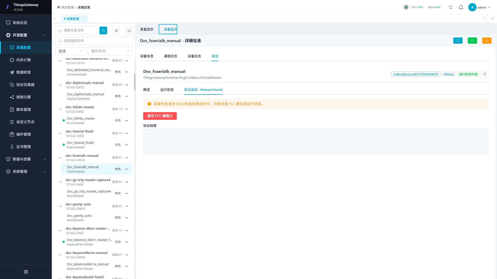
Debugging notes
Check the PLC type first; activating PLC is a high-risk control and must be confirmed twice before execution.
Verify the configuration
- Read a known WORD address such as
D100and compare it with the PLC programming software. - Read a bit address such as
M0; verifyXandYaddresses using octal numbering. - For a Boolean block write, use a safe test area and confirm that the start address and length are both aligned to 16 points.
- Run Activate PLC only during an approved maintenance window after confirming that the field procedure allows it.
Troubleshooting
- Address read has no response: Check the serial or transparent-TCP settings and confirm that the new command/address mapping option matches the PLC series.
XorYaddress is wrong: Recheck that the address is interpreted as octal, not decimal.- Boolean block write fails: Confirm 16-point alignment for both the start address and length.
- PLC activation fails: Confirm that the controller supports the command and that its current state allows activation; inspect the device response.
- The serial port device does not respond: Confirm that the port is not occupied and that baud rate, data bits, stop bits, and parity match the PLC.
Related links
- Collection configuration: View channel, device and common variable configuration.
- Plugin Index: Find other collection or data-forward plugins.