InovanceMaster
Purpose
Inovance PLC Modbus and dedicated address model collection driver
Open the plugin
Enter "Development Configuration → Collection Configuration", create a device and select "InovanceMaster" in "Collection Plugin".
Supported channels and data types
| Channel type | Pre-configuration check |
|---|---|
| Serial Port | Confirm that the serial port is not occupied by other programs and maintains the same baud rate, data bits, stop bits and parity bits as the device. |
| TCP Client | Confirm network reachability of the device IP, port, and gateway to the device. |
| TCP server | Confirm that the local listening address and port are available, and allow on-site devices to actively connect to the gateway. |
Optional data types: Boolean, Byte, Int16, UInt16, Int32, UInt32, Int64, UInt64, Float, Double, String, Decimal
Plugin properties
Protocol parameters
| Setting | Description |
|---|---|
| Inovance Type | Default: 0; fill in: drop-down selection. Set the Inovance type used for protocol communication. |
| Modbus type | Default: ModbusTcp; fill in: drop-down selection. Set the Modbus type used for protocol communication. |
| Default station number | Default: 1; fill in: text input. Set the default station number used when the station number is not specified separately in the variable address. |
Request packing
| Setting | Description |
|---|---|
| FC1 Maximum number of read coil bits | Default: 1600; Range: 1~2000; Fill in: text input. Set the maximum number of FC1 read coil bits used for a single read or write or group packet. |
| FC2 Maximum number of read discrete input bits | Default: 1600; Range: 1~2000; Fill in: text input. Set the maximum number of read discrete input bits used by FC2 for a single read or write or group packet. |
| FC3 Maximum number of read holding registers | Default: 100; Range: 1~125; Fill in: text input. Set the maximum number of FC3 read holding registers used for a single read or write or group package. |
| FC4 Maximum number of read input registers | Default: 100; Range: 1~125; Fill in: text input. Set the maximum number of FC4 read input registers used for a single read and write or group package. |
| FC15 Maximum number of coil bits written in batches | Default: 1968; Range: 1~1968; Fill in: text input. Set the maximum number of FC15 batch write coil bits used for a single read or write or group packet. |
| FC16 Maximum number of batch write registers | Default: 123; Range: 1~123; Fill in: text input. Set the maximum number of FC16 batch write registers used for a single read or write or group package. |
Connection configuration
| Setting | Description |
|---|---|
| DTU ID | Fill in: text input. Sets the identifier used to identify the current device connection through the DTU service. |
Address rules
- AM series
- Q0.0
- IX0.0
- MX0.0
- MW0
- MD0
- MB0
- SM0
- SD0
- s=2;SD0 supports additional specified station number
- H3U
- M0
- SM0
- S0
- T0
- C0
- X0
- Y0
- D0
- SD0
- R0
- s=2;SD0 supports additional specified station number
- H5U
- M0
- B0
- S0
- X0
- Y0
- D0
- R0
- s=2;D0 supports additional specified station number
Functions
| Function | Purpose |
|---|---|
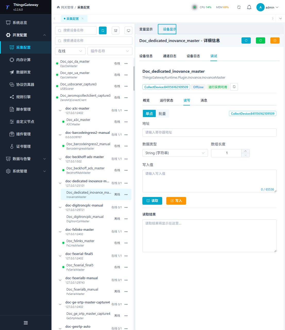
| Read and write | Read a confirmed point and write only to an approved test point. |
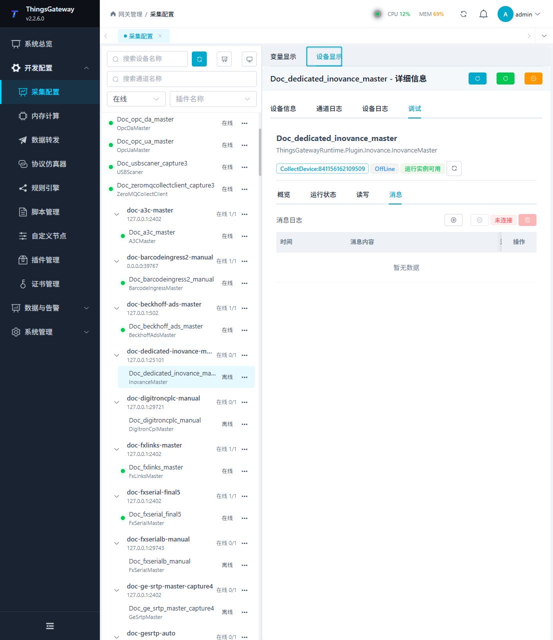
| Messages | View sent and received frames, protocol fields, and error details. |
Device debug
Enter "Development Configuration → Collection Configuration", select the current device and click "More Functions", then open "Debug".
Dedicated debugging page
Open Development Configuration → Collection Configuration, select the device, and open More Functions → Debug. The following image shows the plugin-specific debug page.
Verify the configuration
Use a confirmed on-site address to perform reading. The return value, data type and byte order should be consistent with the point list; after the writable point is written, it should be read back according to on-site requirements.
Troubleshooting
- Address reading failed: Check the station number, register or node ID one by one according to the address rules on this page, and confirm that the data type is consistent with the device point list.
- The serial port device does not respond: Confirm that the serial port is not occupied, and check the baud rate, data bits, stop bits and parity bits.
Related links
- Collection configuration: View channel, device and common variable configuration.
- Plugin Index: Find other collection or data-forward plugins.