Rule Engine
The rule engine is used to process collected data, memory variables, and external events through a visual process. Users can drag trigger nodes, check nodes, compute nodes, push nodes, etc., into the canvas, organize execution sequences by connecting lines, then save and activate workflows.
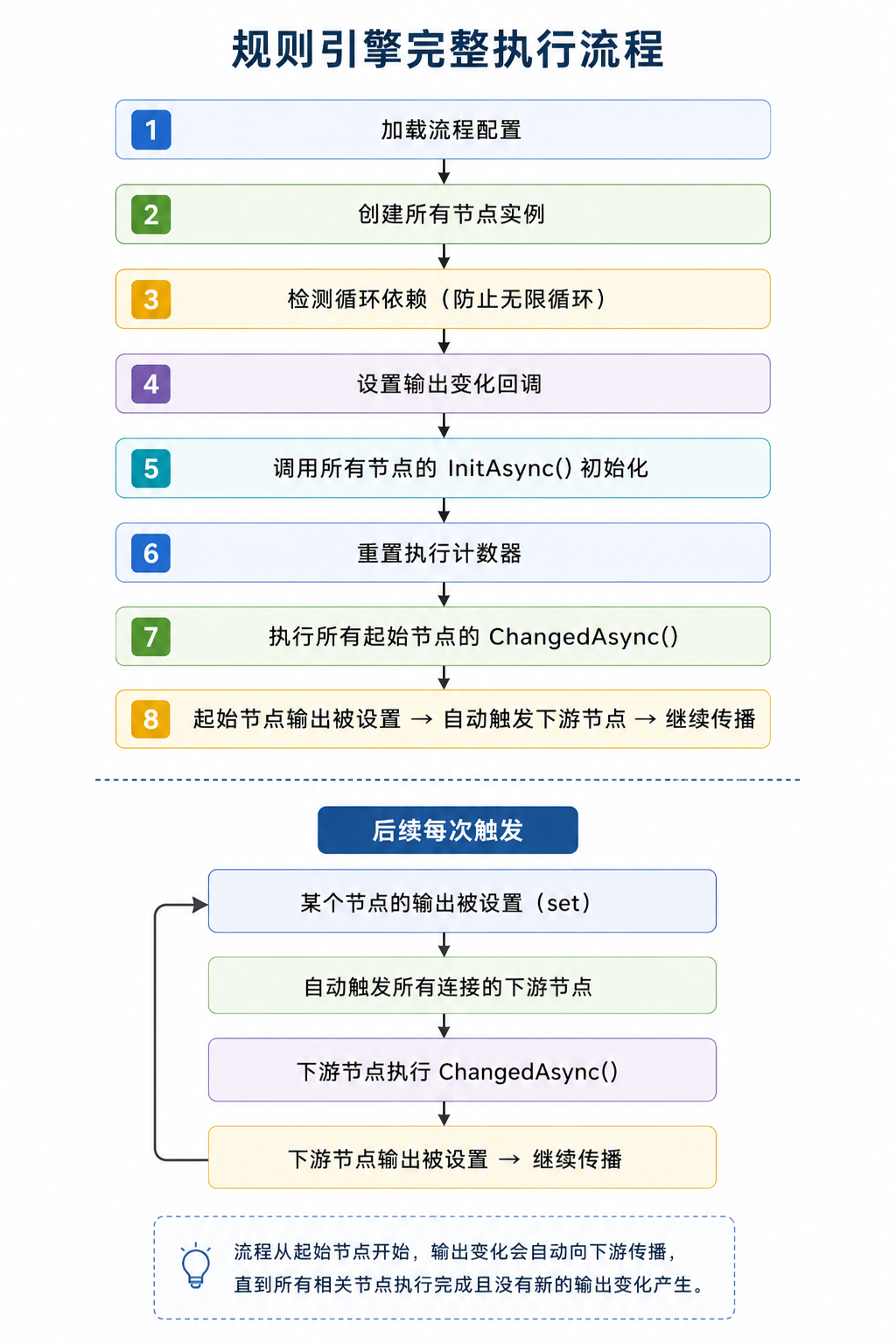
First, look at the terminology
| Terminology | On-site understanding |
|---|---|
| Rules and flows | A set of automated processing logic, For example, "After pressure changes, determine whether to trigger an alarm and write the result to a memory variable." |
| Node | A processing step in the process, similar to a functional block in an electrical diagram. |
| Trigger Node | Decide when the process will start executing, such as variable changes, timed triggers, or external event triggers. |
| Judgment node / Calculation node / Push node | Used respectively to judge conditions, calculate results, and send results to downstream systems or other nodes. |
| Canvas | Drag-drop nodes, line connections, and layout adjustment editing areas. |
| Connection | data transfer relationships between nodes. The direction is usually connected from the upstream output port to the downstream input port. |
| Input / Output / Input/Output Parameters | Input is the data received by the node, output is the result processed by the node, and input and output parameters can be modified by the node and continued to be passed. |
| Stabilization | Repeatedly triggered within a short time frame to avoid frequent process execution when the same value fluctuates rapidly. |
| CSV | Import and export files for a single process canvas, suitable for backing up nodes, wiring, and layout. |
Function Entry
After logging into GatewayRuntime Web, click the left menu "Develop Configuration → Rule Engine".
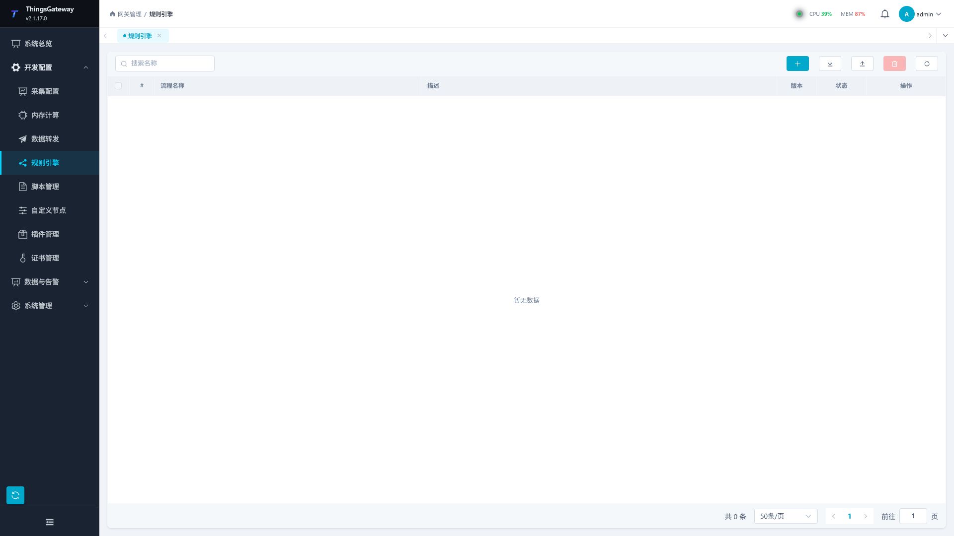
Process List
Rule Engine List is used to manage basic process information, start-stop status, and batch import and export.
| Area or column | Description |
|---|---|
| Search name | Query list by process name. After entering keywords, pressing Enter or clearing the input box will refresh the results. |
| Add rules | Create new rule flows. The page will first ask you to enter the process name, and after successful creation, the process editor will automatically open. |
| Export Excel | Export rule flow configuration according to current search criteria, suitable for backup, migration, and batch maintenance. |
| Importing Excel | Import rule flow from Excel files. After the import is complete, the page will display the number of successes or reasons for failure. |
| Batch Delete | After checking the process, batch delete the files. Before deletion, confirm that the process is no longer involved in production operations. |
| Refresh | Reload the flow list and available custom nodes. |
| Process Name | Rule Process Name. The name should reflect the purpose of the process and facilitate log checking. |
| Description | Process Purpose Description. The list shows - when empty. |
| Version | Process version number. The new creation process starts by default from v1. |
| Status | shows "Enabled" or "Disabled." |
| Operation | "Details" to enter the process editor; In "More," you can enable, disable, or delete workflows. |
New Process
- Click "Add Rule" in the upper right corner of the list.
- Enter the process name in the prompt box.
- After clicking Confirm, the system creates the default enabled
v1flow and enters the process editor. - Maintain process descriptions, trigger methods, nodes, wiring, and parameters in the editor.
- Click "Save" in the upper right corner. After a successful save, the rules engine will reload the process.
Process Editor
Click "Details" in the flow line to enter the process editor.
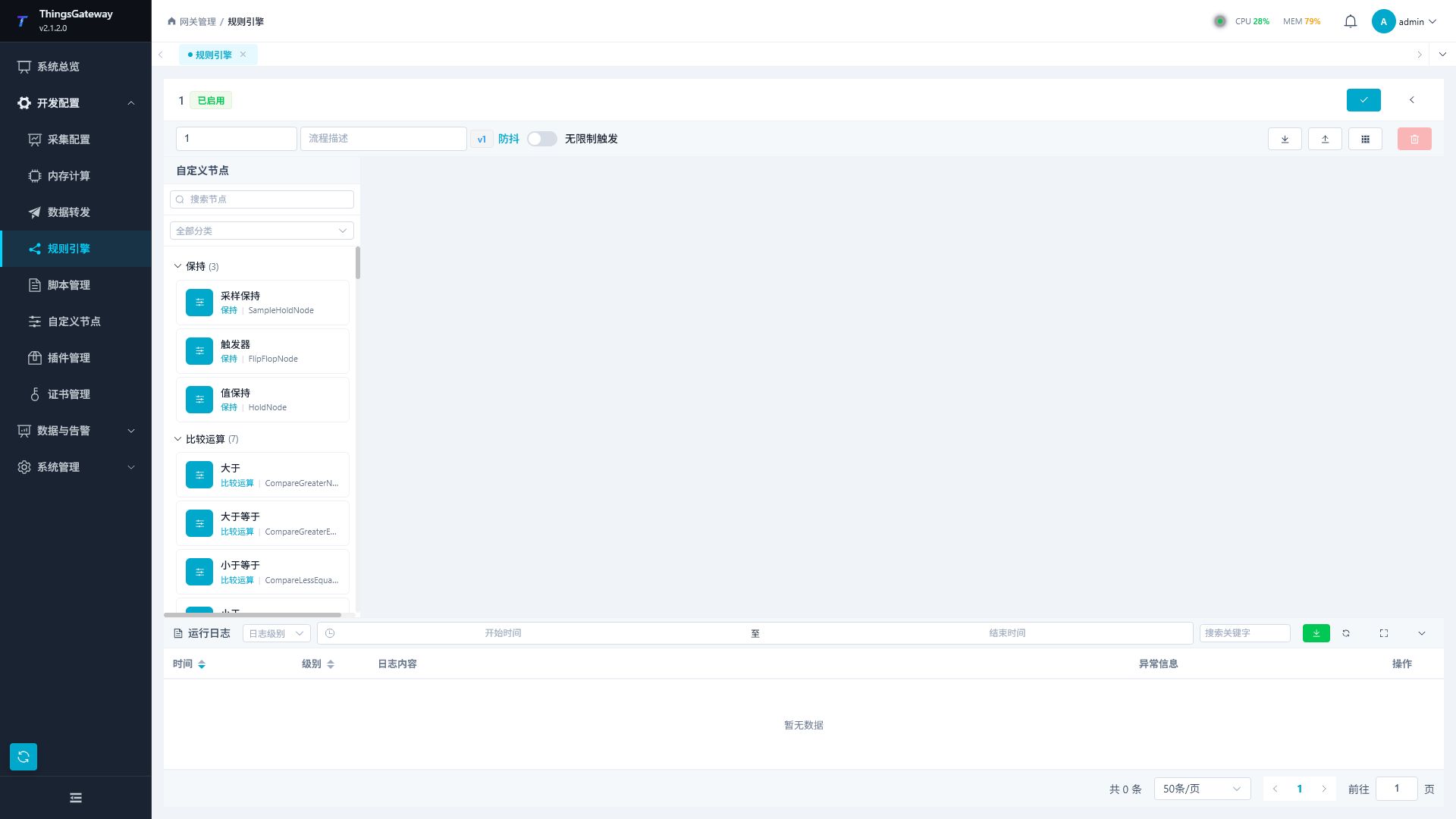
| Area | Description |
|---|---|
| Top Information Area | Displays process name, process description, version number, and trigger method. Process names and descriptions can be directly edited. |
| Save Button | Save the current flow name, description, trigger method, canvas nodes, connections, and node parameters. |
| Back button | Returns the list of rule flows. Before leaving, make sure the current modifications have been saved. |
| Stabilization / Unlimited Triggers | "Stabilization" merges short-term repeated changes; "Unlimited trigger" directly triggers downstream nodes with each change. |
| Export CSV | Export nodes, connections, positions, and node properties from the current editor canvas, suitable for backup of a single workflow structure. |
| Import CSV | Restore the current process canvas from the CSV file. After importing, check the node type, wiring, and parameters before saving. |
| Auto-Layout | Rearrange the canvas based on the current nodes and connections. Used when there are many nodes or intersecting wiring. |
| Delete the selected | Delete the currently selected node or line. |
| Left node panel | Displays available nodes by category, supports searching by node name and filtering by category. |
| Middle Canvas | Drag nodes, connect ports, adjust layout, select nodes or wiring. |
| Right Properties Panel | Displays after selecting a node, used to edit node names, view node types, and fill in input and input parameters. |
| Runtime Log Panel | View the rule engine runlogs, supports filtering by level, time range, and keyword, and exports the current page or all logs. |
Node Panel
Nodes in the node panel come from loaded built-in nodes and custom nodes. Common categories include holding, comparison operations, edge detection, variable RPC, constants, flip-flops, timers, counters, type conversion, logical operations, data statistics, data push, mathematical operations, conditional checks, and string processing.
| Operation | Description |
|---|---|
| Search Node | Enter the node name or identification keyword in "Search Node", Quickly locating nodes. |
| Category Filtering | Select a category in the "All" dropdown to display only nodes under that category. |
| Expand/Collapse Groups | Click the category title to expand or collapse node groups. |
| Add node | Drag nodes from the left panel onto the canvas. After dragging in, select the node and check the parameters in the properties panel. |
If a node does not appear in the list, first confirm that the corresponding script or custom node has been successfully compiled, then refresh the rules engine page.
Canvas Operations
| Operations | Steps |
|---|---|
| Add Nodes | Drag nodes from the left node panel onto the canvas. |
| Connect to Nodes | Drag from one node port to another to establish data transfer relationships. The connection direction should point from the upstream output port to the downstream input port. |
| Configure Nodes | Select the node and modify the node name, input parameters, and input/output parameters in the right properties panel. |
| Rename the node | Double-click the node on the canvas to enter the new node to display the name. |
| Delete nodes or connections | After selecting nodes or connections, click "Delete and Select". |
| Auto Layout | Click "Auto Layout" to have the system rearrange nodes according to the current connection relationships. |
| Save Process | Click "Save" in the upper right corner to save the current canvas and parameters. |
Node Parameters
Node parameters are determined by the node type. Different nodes display different inputs, outputs, and input/output parameters.
| Parameter Type | Description |
|---|---|
| Input Parameter | Receive data from the upstream node, You can also enter the initial value in the properties panel. |
| Output Parameter | The output value processed by the node can be connected to downstream nodes. |
| Input/Output Parameters | Can receive upstream data and continue output after node processing. |
| Customizable initial input parameters | Some nodes support filling initial input values in the properties panel, used for scenarios without upstream input or default values. |
OutputOnlyOnChange | true |
| Real-time Parameter Values | After the process is enabled and running, the property panel and node port display the input, output, and input/output values of the current node. |
When configuring parameters, confirm that data types, variable names, device names, and upstream and downstream nodes match. When connection fails or runtime results are abnormal, prioritize checking port direction, parameter names, parameter types, and process enabled status.
Variable, Event, and Writeback Nodes
These nodes consume Gateway variable, alarm, and device-status events directly. Event nodes do not require an upstream input. After the process is enabled, they wait for the corresponding event and emit only when all filters match. Separate multiple names or enum values with commas; leave a filter empty to match all values.
Variable Notification Rule
The Variable Notification Rule node under Trigger listens for value changes from online variables. Use it to feed collection values into threshold checks, recording, or notification flows. A successful match emits both the current value and the complete variable data object.
| Direction | Parameter | Default | Description |
|---|---|---|---|
| Input | DeviceNames | Empty | Device-name list separated by commas. Empty matches all devices. |
| Input | VariableNames | Empty | Variable-name list separated by commas. Empty matches all variables. |
| Input | CollectGroups | Empty | Collection-group list separated by commas. Empty matches all groups. |
| Output | Result | - | The current Value of the matched variable. Connect it to numeric, logic, or conversion nodes. |
| Output | VariableBasicData | - | The complete variable data object. Connect it to Data or InputData on Webhook, email, or MQTT nodes. |
Offline variables do not trigger this node. Use VariableBasicData when the downstream payload needs the device name, variable name, collection group, online state, change time, or collection time.
Alarm Notification Rule
The Alarm Notification Rule node under Trigger listens for alarm lifecycle events and filters them by level, device, event type, and alarm type. A match emits the original alarm object through FilteredAlarmData.
| Direction | Parameter | Default | Description |
|---|---|---|---|
| Input | MinAlarmLevel | 0 | Ignore alarms below this level. 0 disables level filtering; the usable range follows the variable alarm configuration. |
| Input | DeviceNames | Empty | Device-name list. Empty matches all devices. |
| Input | EventTypes | Empty | Restart, PrepareAlarm, Alarm, PrepareFinish, Finish, Confirm, or ConfirmAndFinish. Empty matches all events. |
| Input | AlarmTypes | Empty | Open, Close, HH, H, L, LL, Custom, or State. Empty matches all types. |
| Input | DebounceMs | 0 | Debounce interval for the same device and variable, in milliseconds. 0 disables debouncing. |
| Input | Enabled | true | Ignore alarm events when disabled. |
| Output | FilteredAlarmData | - | The matched alarm object. Connect it to a notification node's Data input. |
Device Notification Rule
The Device Notification Rule node under Trigger listens for device-status changes. It is useful for offline alarms, recovery notices, and routing by collection plugin.
| Direction | Parameter | Default | Description |
|---|---|---|---|
| Input | DeviceNames | Empty | Device-name list. Empty matches all devices. |
| Input | DeviceStatuses | Empty | OnLine, OffLine, or Pause. Empty matches all statuses. |
| Input | PluginNames | Empty | Collection-plugin name list. Empty matches all plugins. |
| Input | DebounceMs | 0 | Debounce interval for the same device, in milliseconds. 0 disables debouncing. |
| Input | Enabled | true | Ignore device-status events when disabled. |
| Output | FilteredDeviceData | - | The matched device data object. Connect it to a notification node's Data input. |
Variable RPC Node
The Variable RPC Node calls a variable's RPC write capability from a rule flow. It resolves the variable by DeviceName and VariableName, converts WriteData to JSON, and invokes the variable runtime RPC. It does not bypass variable permissions or call a driver directly.
| Direction | Parameter | Description |
|---|---|---|
| Input | DeviceName | Target device name. It must exactly match the running device. |
| Input | VariableName | Target variable name. The variable must expose executable RPC/write capability. |
| Input | WriteData | Scalar, object, or array value or method arguments passed as JSON. |
| Output | Result | OperResult<object> operation result. Connect success or failure handling to a condition or log flow. |
Place this node after a rising-edge, button, or interlock check to avoid repeated writes from high-frequency changes. Verify Result, the variable-write log, and the actual device action. Missing variables, disabled permissions, or paused devices produce a failed result.
MQTT Client Upload Node
The Mqtt Client Upload node under Data Push creates an MQTT client during process initialization and publishes InputData as UTF-8 JSON whenever that input changes. It supports TCP MQTT and WebSocket MQTT. When a send detects a disconnected client, it reconnects with waits growing from 1 second up to 60 seconds.
Parameters
| Direction | Parameter | Default | Description |
|---|---|---|---|
| Input | Url | mqtt://127.0.0.1:1883 | MQTT endpoint. TCP accepts mqtt:// or tcp://; WebSocket accepts ws://, wss://, mqtt-ws://, or mqtt-wss://. |
| Input | Topic | data/upload | Publish topic. |
| Input | UserName / Password | Empty | MQTT credentials. The password is not written to the runtime log. |
| Input | ClientId | Empty | Client identifier. Empty generates a random identifier for each connection. Use a stable value for broker persistent sessions. |
| Input | Retain | false | Retain the last message. Enable only when new subscribers should receive the previous value. |
| Input | Enabled | true | Allow publishing. The node still prepares its connection during process initialization. |
| Input | KeepAlive | 60 | MQTT keep-alive interval in seconds. |
| Input | CleanSession | true | Use a clean session. Disable it with a stable ClientId when a persistent session is required. |
| Input | MqttProtocolVersion | V311 | MQTT protocol version supported by the broker. |
| Input | QosLevel | AtMostOnce | QoS: AtMostOnce (0), AtLeastOnce (1), or ExactlyOnce (2). |
| Input | UseSSL | false | Enable TLS. |
| Input | SslTargetHost | Empty | TLS target host; empty uses the host in Url. |
| Input | SslClientCertificateName | Empty | Client certificate name for mutual TLS. |
| Input | SslCACertificateName | Empty | Custom CA certificate name. |
| Input | SslAllowUntrusted | true | Accept untrusted certificates. Disable this in production and configure a trusted CA. |
| Input | SslProtocols | None | TLS protocol selection; None uses system negotiation. |
| Input | SslCheckCertificateRevocation | false | Check certificate revocation status. |
| Input | InputData | - | Upstream object, array, or scalar serialized as the message payload. |
| Output | Success | false | true after the latest connection or publish succeeds. |
| Output | ErrorMessage | Empty | The latest connection or publish error; cleared after success. |
Minimal Setup and Verification
- Drag in the node and fill in
UrlandTopic; add credentials if the broker requires them. - Connect a variable, alarm, or calculation output to
InputData. - Save and enable the process, then confirm
Successbecomestrue. - Subscribe to the same topic with an MQTT client and check the JSON payload and QoS.
For connection or publish failures, inspect ErrorMessage and the runtime log. Do not use SslAllowUntrusted=true as a permanent production certificate strategy.
Email Push Node
The Email Push node under Data Push sends rule data through SMTP. It creates an SMTP channel on the first send or after the mail configuration changes. Each send has a 10-second timeout.
Parameters
| Direction | Parameter | Default | Description |
|---|---|---|---|
| Input | Host | Empty | SMTP server address. |
| Input | Port | 587 | SMTP server port. |
| Input | EnableSsl | true | Enable SMTP encryption. |
| Input | UserName / Password | Empty | SMTP credentials. |
| Input | FromAddress | Empty | Sender address. |
| Input | FromName | ThingsGateway | Sender display name. |
| Input | ToAddresses | Empty | Recipient addresses separated by commas. |
| Input | SubjectTemplate | 告警通知 - {{DeviceName}} - {{EventType}} | Subject template. Use {{PropertyName}} for properties of Data; empty uses the default template. |
| Input | BodyTemplate | Default HTML alarm table | Body template with {{PropertyName}} replacement. A body beginning with < is sent as HTML; empty uses the default template. |
| Input | Enabled | true | Allow sending. |
| Input | Data | - | Upstream object, array, or scalar. |
| Output | Success | false | Result of the latest mail send. |
| Output | ErrorMessage | Empty | Error from disablement, missing data, SMTP configuration, or sending. |
| Output | LastPushTime | Unix epoch | UTC time of the latest completed send attempt. |
Minimal Setup and Verification
- Fill in the SMTP host, port, credentials, sender, and at least one recipient.
- Connect an alarm-rule or other object output to
Data. - Adjust the subject or body template for the receiver, then save and enable the process.
- Trigger a test event. Confirm
Success=true, an emptyErrorMessage, and the expected substituted fields in the mailbox.
For authentication, certificate, or recipient errors, inspect ErrorMessage and check the server port, SSL mode, and sender policy. Do not record passwords in rule logs or public documentation.
Webhook Push Node
The Webhook Push node under Data Push sends rule results to a DingTalk custom robot, a WeCom message-push webhook (formerly group robot), or a custom HTTP endpoint. Platform is an explicit selector in the properties panel; the node does not infer a vendor from the URL.
Parameters
| Direction | Parameter | Description |
|---|---|---|
| Input | Url | Complete Webhook URL. DingTalk URLs contain access_token; WeCom URLs contain key. |
| Input | Platform | DingTalk, WeCom, or Custom; new nodes default to Custom. |
| Input | Headers | Custom request-header JSON, such as {"Authorization":"Bearer <token>"}. Usually empty for DingTalk and WeCom. |
| Input | BodyTemplate | Complete JSON request-body template. Use {{PropertyName}} to reference Data properties. |
| Input | Secret | A SEC... signing secret for DingTalk robot signing. Leave empty for WeCom and Custom. |
| Input | Enabled | Allow the node to send requests. |
| Input | Data | Upstream object, such as VariableBasicData, AlarmVariable, or a custom object. |
| Output | Success | true only when HTTP and the vendor business response both succeed. |
| Output | ErrorMessage | Latest send failure; cleared after success. |
| Output | LastPushTime | UTC time of the latest completed send attempt. |
Placeholders inside JSON strings escape quotes, backslashes, and line breaks. Placeholders used as JSON values preserve number, Boolean, array, or object types. A missing property becomes empty text inside a string and null in a value position.
{
  "device": "{{DeviceName}}",
  "message": "{{AlarmText}}",
  "level": {{AlarmLevel}},
  "value": {{Value}}
}
DingTalk
- Set
PlatformtoDingTalk. - Enter the complete
https://oapi.dingtalk.com/robot/send?access_token=<robot-token>URL inUrl. - Fill in
Secretonly when the robot uses signing; leave it empty for keyword or IP allowlist security. - Use the default text body or a DingTalk Markdown body such as:
{
  "msgtype": "markdown",
  "markdown": {
    "title": "Gateway alarm",
    "text": "## {{DeviceName}}\n\n{{AlarmText}}"
  }
}
The node appends timestamp and sign using DingTalk HmacSHA256 rules. Do not add them manually. After HTTP 2xx, it also checks the JSON response; Success=true requires numeric errcode 0 (or the string "0").
WeCom
- Set
PlatformtoWeCom. - Enter the complete
https://qyapi.weixin.qq.com/cgi-bin/webhook/send?key=<message-key>URL inUrl. - Leave
Secretempty. The default text body can be used directly. - WeCom Markdown uses
markdown.content, not DingTalk'stitleandtextfields:
{
  "msgtype": "markdown",
  "markdown": {
    "content": "# {{DeviceName}}\n{{AlarmText}}"
  }
}
The node requires HTTP 2xx and a WeCom response with an integer errcode of 0 before setting Success=true.
Frequency and Security
DingTalk robots and WeCom message webhooks are limited to 20 messages per minute. For high-frequency variables, add an edge, threshold, hold, timer, or aggregation node before Webhook and send a summary. Webhook URLs contain credentials; do not put them in logs, screenshots, public documentation, or source control.
Trigger Method
| Configuration | Recommended Usage |
|---|---|
| Stabilization | Suitable for high-frequency data changes such as temperature, pressure, and liquid level, reducing repeated execution in a short period. |
| Unlimited triggers | Suitable for scenarios where counting, accumulation, event logging, and other changes require handling every change. |
Enabling "Unlimited Triggering" may increase runtime. Before use in a production environment, the frequency of variable changes, process complexity, and downstream system load capacity should be first evaluated.
Import and Export
Rule engines have two types of import and export entries, each with different scopes.
| Entry | Location | Purpose |
|---|---|---|
| Export Excel | Process List Toolbar | Export process list configuration, suitable for batch backup and migration of multiple processes. |
| Import Excel | Workflow List Toolbar | Batch import workflows from Excel. After importing, you should open the details to check each process. |
| Export the CSV | Process Editor Toolbar | Export the current flow canvas nodes, lines, positions, and node properties. |
| Import the CSV | Process Editor toolbar | Restore the current flow canvas structure. After importing, check the nodes, wiring, and parameters. |
| Export Logs | Run Log Panel | Export the current page or all rule run logs for troubleshooting and archiving. |
Before importing, it is recommended to have a pre-existing process as a backup. Do not enable production immediately after importing; instead, open the process editor first to check node type, wiring direction, parameter values, and runlogs.
Runlog
Rule Flow After running, you can view the runtime log at the bottom of the editor.
| Functionality | Description |
|---|---|
| Log Level | Filtering by log level, such as Trace, Debug, Info, Warning, Error. |
| Time Range | Filter logs by start and end time. |
| Keywords | Search by log content keywords. |
| Export | Export the current page or all match logs. |
| Refresh | immediately reload the log. When the process is enabled, the log panel automatically refreshes at fixed intervals. |
| Maximize/restore | Expand the log panel for easier viewing of long logs. |
| Fold/Unfold | Temporarily fold the log panel to free up more space on the canvas. |
| Details | Open the log details drawer to view the log content and anomalies. |
Common Process Design
| Scenarios | Design Methods |
|---|---|
| Single Path Processing | Trigger or Input Nodes → Processing Nodes → Output Nodes. |
| Branch Processing | A single processing node connects multiple downstream nodes and simultaneously executes alarm decisions, data logging, or message pushes. |
| Multi-condition Comprehensive Judgment | Multiple input or processing nodes connect to the same judgment node, which outputs the result. |
| Periodic tasks | Use timer-type nodes to trigger periodic calculations or periodic pushes. |
| External Push | Use data push nodes such as Webhook, MQTT, and email to send processing results to external systems. |
| Circular relationships | Avoid forming closed-loop connections at nodes. When state memory is needed, prioritize using holds, counters, memory variables, or dedicated handling nodes. |
Usage Notes
| Scenarios | Recommendations |
|---|---|
| Production Modification Process | Export the process before modification, save it, and observe the runlog. |
| node cannot be found | Confirm that the custom node has been successfully compiled, and refresh the page if necessary. |
| Flow does not execute | Check whether the process is enabled, whether the trigger node has received data, and whether the wiring direction is correct. |
| Node parameters are empty | After selecting the node, check the properties panel and confirm that input parameters, input/output parameters, and default values are configured. |
| Results do not meet expectations | View real-time node parameter values and locate segment by segment from upstream to downstream. |
| Log is empty | Confirm that the process is enabled and actually triggered; Then check the log level and time range filter conditions. |
| System load increases | Check high-frequency trigger processes, complex compute nodes, external push nodes, and "unlimited trigger" configurations. |
Fault Handling
| Phenomenon | Handling Recommendations |
|---|---|
| Failed Save | Check whether the process name is empty and whether node parameters are valid, and check the page error message. |
| Node Exceptions After CSV Import | Check if the imported file comes from the same version of the flow editor and confirm that the custom node name still exists. |
| port cannot connect | Confirm that the connection direction matches the parameter type, avoiding connecting output ports to output ports or input ports connecting to input ports. |
| Real-time parameter values are not displayed | Confirm that the process is enabled and triggered to run; Unrun processes do not generate real-time node values. |
| Persistent log errors | Open log details to check the exception information, then return to the corresponding node to check parameters, scripts, and external connections. |
Related Links
- Collection Configuration - Channel, Device, Variable Configuration
- Memory Calculation - Common Memory Variables for Maintenance Rule Flow
- Custom Nodes - Custom Node Management
- Script Management - Script Development and Management