Modbus Server
Purpose
This target exposes variables from a forwarding group to an external Modbus master through Modbus TCP or Modbus RTU. The current Modbus type list has no ASCII option.
Configure the forwarding group and target through Data Forwarding. This page covers Modbus server properties, address mapping, client permissions, and protocol debug.
Open the plugin
Open Development Configuration → Data Forwarding and:
- Save the forwarding-group variable range.
- Add a target, choose Modbus Server, and fill in its basic target information.
- Open Target properties, choose the Modbus type and channel, then configure protocol, permissions, serial, DTU, or TLS settings.
- Save the target and configure a required Slave variable address for each exposed variable.
- Enable the target and verify with an external Modbus master or the debug page.
Basic target information
| Setting | Default | Configuration |
|---|---|---|
| Group | - | Select a saved forwarding group. |
| Target name | - | Required and unique within the group. |
| Enable | Enabled | Disable to stop listening. |
| Log level | Info | Temporarily use Debug for protocol diagnostics. |
| Start timeout | 60 seconds | Valid range is 1 to 3600 seconds. |
Target properties
Protocol
| Setting | Default | Configuration |
|---|---|---|
| Modbus type | ModbusTcp | Current choices are ModbusTcp (MBAP) and ModbusRtu (binary RTU + CRC16). TCP normally uses TcpService; RTU normally uses SerialPort. |
| Default station | 1 | Used when an address has no S= prefix. |
| Multiple-station mode | Enabled | Allows multiple stations in one target. |
| Channel type | TcpService | Select TcpService, SerialPort, or the channel required by the deployment. |
Data format
| Setting | Default | Configuration |
|---|---|---|
| Data format | ABCD | Select ABCD, BADC, CDAB, or DCBA to match the external master. |
| Reverse string bytes | Disabled | Reverse string bytes by word only when required by the external layout. |
Permissions
| Setting | Default | Configuration |
|---|---|---|
| Allow RPC write | Enabled | Target-level write switch. Disable for read-only monitoring. |
| Client permission list | Empty | Empty allows all TCP client IPs. When non-empty, only matching AllowedClientIp entries connect; AllowWrite must also be true for writes. |
Runtime
| Setting | Default | Configuration |
|---|---|---|
| Write to memory immediately | Enabled | Applies an accepted write to the gateway variable immediately. |
| Send delay | 0 ms | Delay before a reply frame when required by the master. |
| Connection timeout | 3000 ms | Connection-operation timeout; minimum 100 ms. |
| Heartbeat content | Empty | Optional application heartbeat content. |
| Heartbeat is Hex | Disabled | Treats heartbeat content as hexadecimal when enabled. |
| Heartbeat interval | 60000 ms | Server heartbeat interval. |
Connection
| Setting | Default | Configuration |
|---|---|---|
| Remote address | 127.0.0.1:502 | Used only when the selected channel requires a remote endpoint. |
| Local bind address | 0.0.0.0:502 | TCP service listen address. Restrict it to a required interface in production. |
| Serial port | COM1 | Used for serial channels. |
| DTU ID | Empty | Identifier used to match a DTU service connection. |
| DTU ID is Hex | Disabled | Parses the DTU ID as hexadecimal bytes when enabled. |
| DTU service type | Default | Select the DTU registration mode required by the terminal. |
TLS
| Setting | Default | Configuration |
|---|---|---|
| Enable SSL | Disabled | Enables TLS for the channel. |
| SSL target host | Empty | Host name used for client certificate validation. |
| SSL client certificate | Empty | Client certificate for mutual TLS. |
| SSL server certificate | Empty | Certificate presented by a server channel. |
| SSL CA certificate | Empty | CA used to validate peer certificates. |
| Allow untrusted certificate | Enabled | Temporary self-signed testing only; disable in production. |
| SSL protocol | None | Keep the system default unless the peer requires a specific TLS version. |
| Check certificate revocation | Disabled | Enable according to the security policy. |
Serial port
| Setting | Default | Configuration |
|---|---|---|
| Baud rate | 9600 | Must match the external master and serial device. |
| Data bits | 8 | Must match the external master. |
| Parity | None | Must match the external master. |
| Stop bits | One | Must match the external master. |
| DTR / RTS | Enabled / Enabled | Hardware flow-control switches. |
| Async stream | Enabled | Enables asynchronous serial I/O. |
| Handshake | Default | Serial handshake mode. |
| Input / output buffer | 4096 / 2048 bytes | Increase only for long or continuous frames. |
Capacity and reliability
| Setting | Default | Configuration |
|---|---|---|
| Maximum concurrency | 1 | Maximum concurrent protocol requests; minimum 1. |
| Maximum connections | 10000 | Maximum client connections. |
| Frame cache time | 500 ms | Frame assembly cache window; minimum 100 ms. |
| Client cleanup time | 120000 ms | Idle-client cleanup interval. |
Target variable properties
| Setting | Description |
|---|---|
| Slave variable address | Required. Modbus address exposed to the external master. |
| Data type | Default Int16. Data type used for this target mapping. |
| Allow RPC write | Allows external clients to write this variable when target-level and channel-level write permissions also allow it. |
The variable must already be inside the forwarding group's range. Adding a target variable property does not add a member to the group.
Address rules
| Address | Data area | Common read function |
|---|---|---|
00001 | Coils | FC1 |
10001 | Discrete inputs | FC2 |
30001 | Input registers | FC4 |
40001 | Holding registers | FC3 |
Addresses use one-based notation. S=2;40001 exposes holding register 40001 at station 2; F=3;0 explicitly uses FC3 with zero-based offset 0; 40001.3 exposes bit 3 of the register.
Within one target, station, function, and start-address combinations must not overlap. Match the data type and register size to the external master's point list.
Functions
| Function | Purpose |
|---|---|
| Read and write | Read a confirmed point and write only to an approved test point. |
| Forwarding pipeline | Use Forwarding pipeline and review the returned result. |
| Protocol service | Use Protocol service to send or inspect protocol frames and view the device or target response. |
Target debug
Open Development Configuration → Data Forwarding, select the forwarding group and target, and open Debug.
Read and write
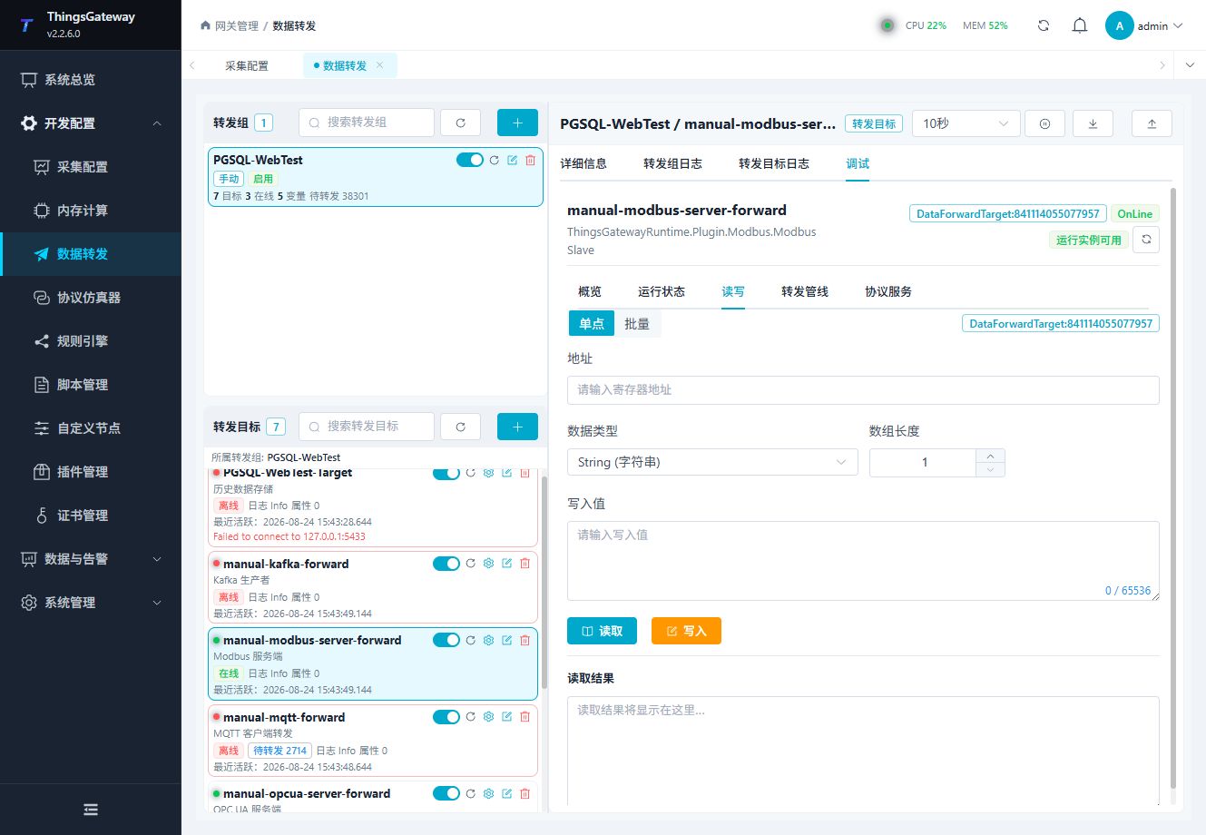
Read a mapped address first. Before writing, confirm target, channel, client, and variable write permissions.
Forwarding pipeline
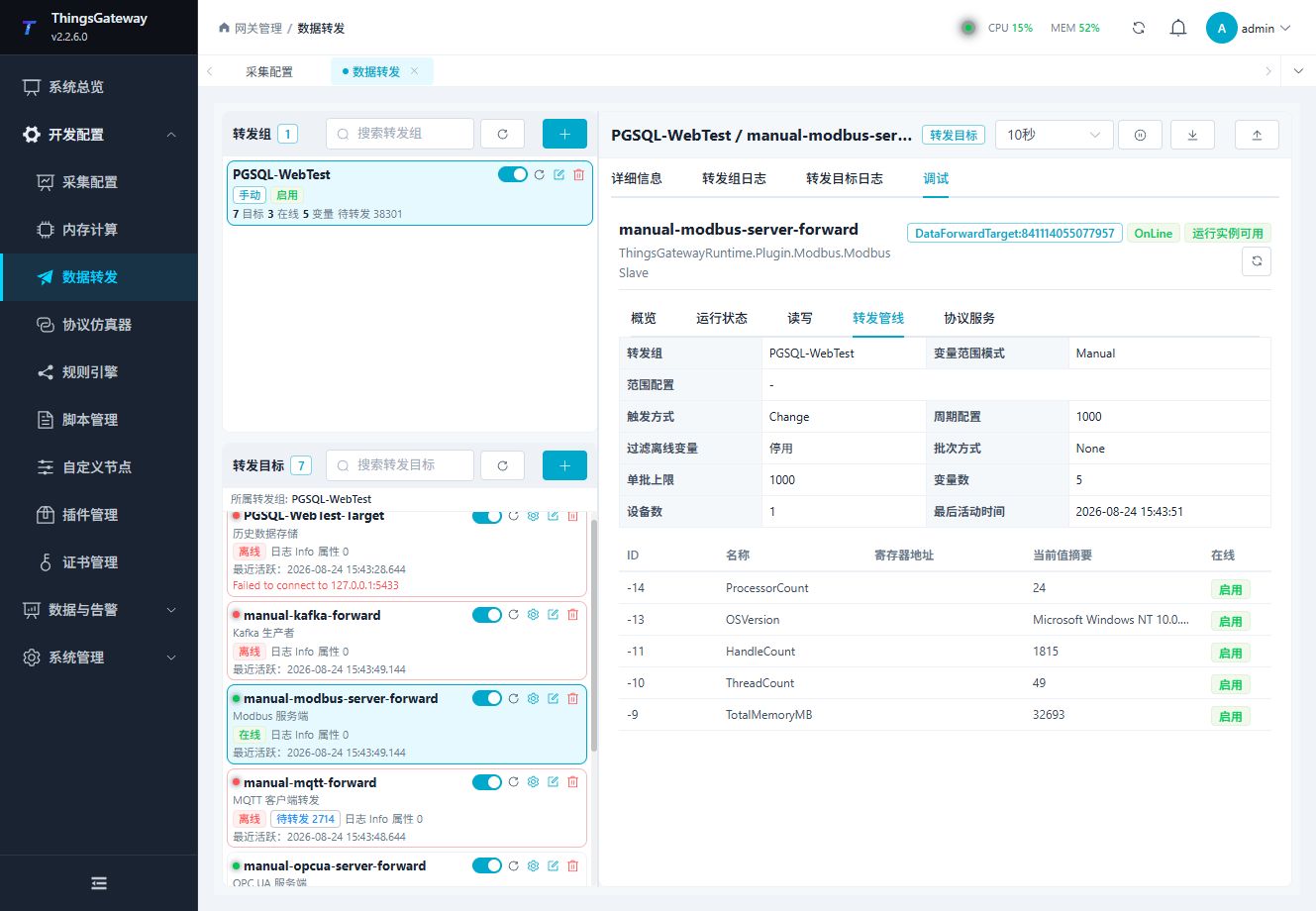
Use the pipeline view to confirm how a group variable becomes an exposed Modbus value.
Protocol service
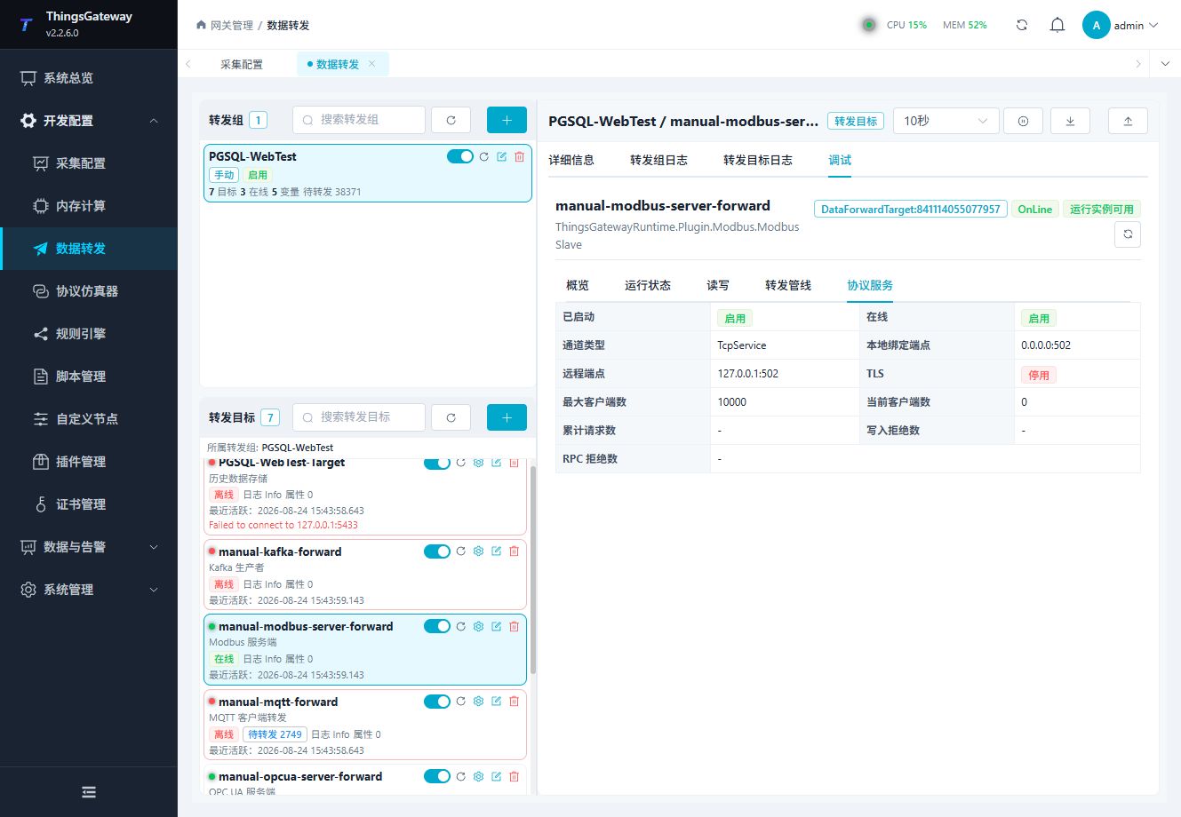
Check the listening endpoint, connected clients, and protocol-service state.
Verify the target
- Start the target and confirm the server is listening.
- Connect an external Modbus master.
- Read one mapped variable in each configured data area.
- If writing is enabled, write one safe value and confirm the gateway variable changes as expected.
Troubleshooting
| Symptom | Check |
|---|---|
| Master cannot read a value | Listening channel, bind address, station, function code, target variable property, and data type. |
| Client cannot connect | Channel type, local bind address, port, firewall, maximum connections, and client permission list. |
| Value has wrong byte order | Data format, string-byte setting, target data type, and external master format. |
| Write is rejected | Target RPC write, variable RPC write, client permission, and the external master's function code. |
| Serial server has no response | Port ownership, baud rate, data bits, parity, stop bits, flow control, and frame timing. |
Related links
- Data Forwarding: Forwarding groups, triggers, cache, redundancy, and common target operations.
- Plugin Manual Index: Other collection and data-forwarding plugins.