On this page
MC 3E ASCII master
Mitsubishi MC 3E ASCII protocol PLC address read and write driver
Open the plugin
Enter “Development Configuration → Collection Configuration”, create a device and select “Mc3E_AsciiMaster” in “Collection Plugin”.
Supported channels and data types
| Channel type | Pre-configuration check |
|---|---|
| Serial Port | Confirm that the serial port is not occupied by other programs and maintains the same baud rate, data bits, stop bits and parity bits as the device. |
| TCP Client | Confirm network reachability of the device IP, port, and gateway to the device. |
| TCP server | Confirm that the local listening address and port are available, and allow on-site devices to actively connect to the gateway. |
| UDP | Confirm the local binding address, port and firewall rules, and check the source of the packet. |
Optional data types: Boolean, Byte, Int16, UInt16, Int32, UInt32, Int64, UInt64, Float, Double, String, Decimal
This list describes types allowed by the plugin editor. Address width, arrays, string length and read/write restrictions still follow this page; it does not mean that every address supports every type.
Plugin properties
Protocol parameters
| Setting | Description |
|---|---|
| Network number | Default: 0; fill in: text input. Set the network number used for protocol communication. |
| IO module station number | Default: 0; fill in: text input. Set the IO module station number used for protocol communication. |
| IO module ID | Default: 1023; fill in: text input. Set the IO module ID used for protocol communication. |
| PLC ID | Default: 255; fill in: text input. Set the PLC ID used for protocol communication. |
Address rules
- MC 3E ASCII bit device area: X, Y, M, S, L, F, V, B, SM, SB, DX, DY, TS, TC, SS, SC, CS, CC.
- WORD device area: D, SD, W, SW, R, Z, ZR, TN, SN, CN.
- WORD area Boolean access must explicitly specify .0 to .15 bit numbers; the bit device area does not accept additional bit numbers.
Device debug
Enter “Development Configuration → Collection Configuration”, select the current device then open “Protocol Debug” at the top of the workspace.
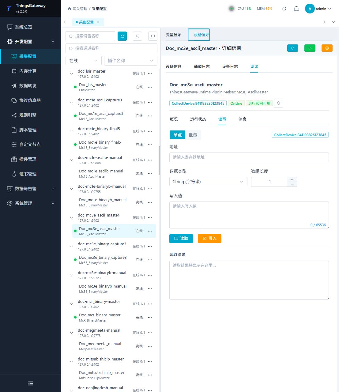
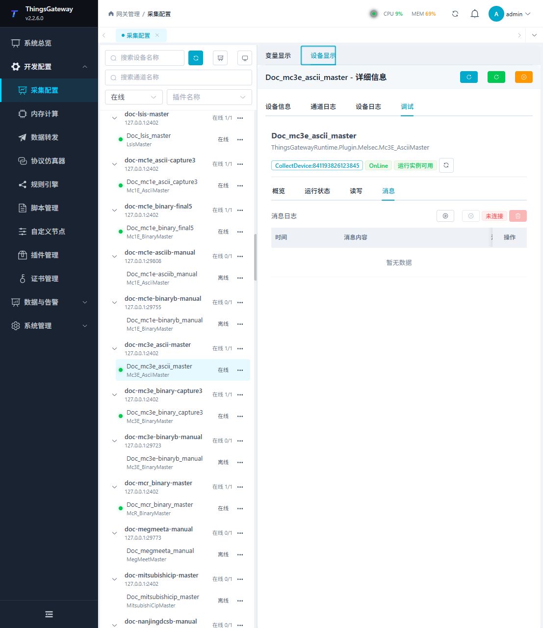
Functions
| Function | Purpose |
|---|---|
| Read and write | Read a confirmed point and write only to an approved test point. |
| Messages | View sent and received frames, protocol fields, and error details. |
Verify the configuration
Monitor D100 online in the PLC engineering tool, compare its value with the gateway variable and confirm advancing sample times.
Troubleshooting
- Match frame generation, ASCII/binary encoding and device-area radix. 1E does not use 3E routing; R extension areas follow the table on this page.
- The serial port device does not respond: Confirm that the serial port is not occupied, and check the baud rate, data bits, stop bits and parity bits.
Related links
- Collection configuration: View channel, device and common variable configuration.
- Plugin Index: Find other collection or data-forward plugins.