On this page
Rule Engine
Try a comparison first
Create a writable Memory.ManualValue using Memory Computation, then use this isolated input for the first flow.
- Create a disabled rule and drag Variable Notification Rule onto the canvas.
- Set
DeviceNames=MemoryandVariableNames=ManualValue; leave other filters empty. - Add Greater Than and set its initial
InputBto100. Add JSON Numeric Extraction, connect notificationResultto itsInput, then connect its numericResultto comparisonInputA. - Validate, save, and enable the flow. Check the loaded revision. Write
101to the memory point, select the comparison, open Runtime, and inspect Real-time Parameter Values: inputs should be101and100, withResult=true. - Write
99and then100; both should producefalse. Writing the same value repeatedly may produce no new change notification. - Disable the practice flow when finished.
The following image locates the Result field on the Runtime tab. The three-node wiring used in this exercise is shown in the subsequent examples.
Set initial inputs on the Configuration tab. View a connected InputA under Runtime → Real-time Parameter Values.
The rule engine is used to process collected data, memory variables, and external events through a visual process. Users can drag trigger nodes, check nodes, compute nodes, push nodes, etc., into the canvas, organize execution sequences by connecting lines, then save and activate workflows.
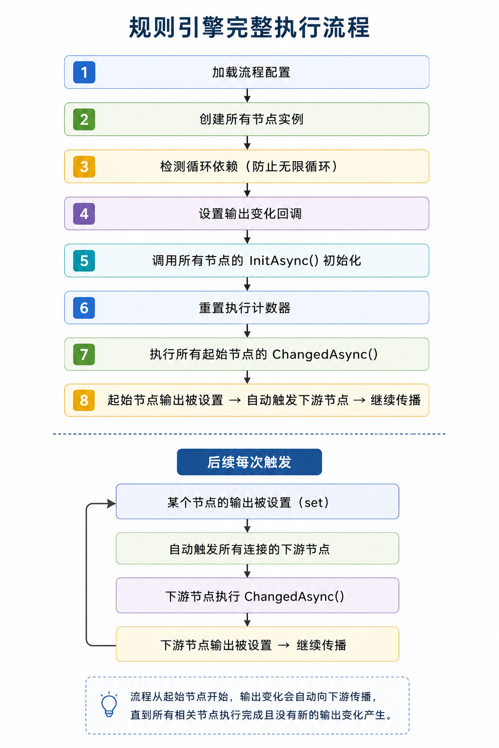
First, look at the terminology
| Terminology | On-site understanding |
|---|---|
| Rules and flows | A set of automated processing logic, For example, “After pressure changes, determine whether to trigger an alarm and write the result to a memory variable.” |
| Node | A processing step in the process, similar to a functional block in an electrical diagram. |
| Trigger Node | Decide when the process will start executing, such as variable changes, timed triggers, or external event triggers. |
| Judgment node / Calculation node / Push node | Used respectively to judge conditions, calculate results, and send results to downstream systems or other nodes. |
| Canvas | Drag-drop nodes, line connections, and layout adjustment editing areas. |
| Connection | data transfer relationships between nodes. The direction is usually connected from the upstream output port to the downstream input port. |
| Input / Output / Input/Output Parameters | Input is the data received by the node, output is the result processed by the node, and input and output parameters can be modified by the node and continued to be passed. |
| Debouncing | Coalesces repeated state changes within a short interval to reduce repeated flow execution. |
| JSON rule package | Backs up flow definitions, layout, dependency information, and redaction lists. |
Function Entry
After logging into TGateway Web, click the left menu “Develop Configuration → Rule Engine”.
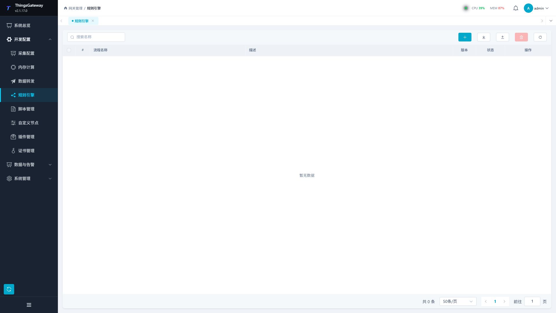
Create and edit a flow
Process List
The rule list manages flow details, enablement, and rule packages. Export production flows before changing them.
| Area or column | Description |
|---|---|
| Search name | Query list by process name. After entering keywords, pressing Enter or clearing the input box will refresh the results. |
| Add rules | Create new rule flows. The page will first ask you to enter the process name, and after successful creation, the process editor will automatically open. |
| Export rule package | Export JSON rule packages using the current name filter. |
| Import rule package | Review each flow and choose create, skip, or replace; inspect the result counts. |
| Batch Delete | After checking the process, batch delete the files. Before deletion, confirm that the process is no longer involved in production operations. |
| Refresh | Reload the flow list and available custom nodes. |
| Process Name | Rule Process Name. The name should reflect the purpose of the process and facilitate log checking. |
| Description | Process Purpose Description. The list shows - when empty. |
| Version | Process version number. The new creation process starts by default from v1. |
| Configuration status | The saved enablement setting. Check the loaded instance separately. |
| Loaded instance | The runtime instance and its loaded definition revision. Check runtime logs if observation fails. |
| Operation | Open Details to validate and enable or disable the flow. |
New Process
- Click “Add Rule” in the upper right corner of the list.
- Enter the process name in the prompt box.
- Click Create Disabled Rule. The system creates a disabled
v1flow and opens the editor. - Maintain process descriptions, trigger methods, nodes, wiring, and parameters in the editor.
- Validate and resolve input, type, and cycle errors. Save the draft, then enable it and check the loaded revision. Disabled drafts may be incomplete, but must pass execution validation before enabling.
Revalidate after editing the draft. If another editor causes a version conflict, keep your changes and compare them with the latest flow before retrying. Saving an enabled flow reloads it; schedule that change for a suitable operating window.
Process Editor
Click “Details” in the flow line to enter the process editor.
| Area | Description |
|---|---|
| Top Information Area | Displays process name, process description, version number, and trigger method. Process names and descriptions can be directly edited. |
| Save Button | Save the flow and canvas. Disabled flows remain drafts; saving an enabled flow reloads it. |
| Back button | Returns the list of rule flows. Before leaving, make sure the current modifications have been saved. |
| Debouncing / No debounce | Debouncing coalesces short-term state changes; No debounce schedules each change without that delay. |
| Validate flow | Check the current draft and locate diagnostics without saving or executing the flow. |
| Enable / Disable | Operate the saved flow. Check the loaded revision after enabling. |
| Connections / Search graph | Add, edit, locate, or split named-port connections; search the whole graph for nodes. |
| Layout and selection | Align, distribute, select upstream or downstream nodes, or create visual groups. Groups organize the layout; connections still determine execution. |
| Auto-Layout | Rearrange the canvas based on the current nodes and connections. Used when there are many nodes or intersecting wiring. |
| Delete the selected | Delete the currently selected node or line. |
| Left node panel | Displays available nodes by category, supports searching by node name and filtering by category. |
| Middle Canvas | Drag nodes, connect ports, adjust layout, select nodes or wiring. |
| Right Properties Panel | Displays after selecting a node, used to edit node names, view node types, and fill in input and input parameters. |
| Runtime Log Panel | View the rule engine runlogs, supports filtering by level, time range, and keyword, and exports the current page or all logs. |
Node Panel
Nodes in the node panel come from loaded built-in nodes and custom nodes. Common categories include holding, comparison operations, edge detection, variable RPC, constants, flip-flops, timers, counters, type conversion, logical operations, data statistics, data push, mathematical operations, conditional checks, and string processing.
| Operation | Description |
|---|---|
| Search Node | Enter the node name or identification keyword in “Search Node”, Quickly locating nodes. |
| Category Filtering | Select a category in the “All” dropdown to display only nodes under that category. |
| Expand/Collapse Groups | Click the category title to expand or collapse node groups. |
| Add node | Drag nodes from the left panel onto the canvas. After dragging in, select the node and check the parameters in the properties panel. |
If a node does not appear in the list, first confirm that the corresponding script or custom node has been successfully compiled, then refresh the rules engine page.
Canvas Operations
| Operations | Steps |
|---|---|
| Add Nodes | Drag nodes from the left node panel onto the canvas. |
| Connect to Nodes | Drag from one node port to another to establish data transfer relationships. The connection direction should point from the upstream output port to the downstream input port. |
| Configure Nodes | Select the node and modify the node name, input parameters, and input/output parameters in the right properties panel. |
| Rename the node | Double-click the node on the canvas to enter the new node to display the name. |
| Delete nodes or connections | After selecting nodes or connections, click “Delete and Select”. |
| Auto Layout | Click “Auto Layout” to have the system rearrange nodes according to the current connection relationships. |
| Save Process | Click “Save” in the upper right corner to save the current canvas and parameters. |
Use Quick Actions for copy, paste, and selection. After copying between flows, check node dependencies, device and variable names, and external connection settings, then validate.
Node Parameters
Node parameters are determined by the node type. Different nodes display different inputs, outputs, and input/output parameters.
| Parameter Type | Description |
|---|---|
| Input Parameter | Receive data from the upstream node, You can also enter the initial value in the properties panel. |
| Output Parameter | The output value processed by the node can be connected to downstream nodes. |
| Input/Output Parameters | Can receive upstream data and continue output after node processing. |
| Customizable initial input parameters | Some nodes support filling initial input values in the properties panel, used for scenarios without upstream input or default values. |
| Real-time Parameter Values | After the process is enabled and running, the property panel and node port display the input, output, and input/output values of the current node. |
Connections bind by port name. State/event semantics, nullability, array shape, and units must agree; use explicit conversion nodes when necessary. Cycles are rejected during validation. Stale save or control revisions require reloading and comparing the current definition before retrying.
Advanced Execution Policy
Select a node, open the Configuration tab, and expand Advanced Execution Policy. These settings govern that node and have no business input ports.
| Parameter | Description |
|---|---|
OutputOnlyOnChange | Defaults to true. State outputs propagate only when the value changes; disable it to propagate every assignment. Event outputs may deliver the same value repeatedly. This setting does not limit sends performed by the node itself. |
ExecutionTimeoutMilliseconds | Default 30000 ms; range 100–600000. Total deadline for one execution, including all attempts and backoff, rather than a fresh timeout for each attempt. |
MaxExecutionAttempts | Default 1; range 1–5, including the initial attempt. Only explicitly recognized transient failures can be retried. Setting 2 does not retry every error. |
RetryBackoffMilliseconds | Default 250 ms; range 0–60000. Base wait before the first retry; subsequent base waits double, capped at 60000 ms. No retry means no backoff. |
RetryJitterMilliseconds | Default 100 ms; range 0–10000. Adds a random wait from zero through this limit to each backoff. Set 0 to disable jitter. |
Allow enough total time for processing and backoff. A deadline does not undo a device write or message already sent. Once device writes, MQTT, email, or Webhook operations have started, an unconfirmed outcome can be UnknownEffect; increasing attempts does not blindly resend them. Check the actual device or receiver first. Business rejection, cancellation, and timeout are not general retry conditions.
Runtime Values and Execution Results
Open Runtime and check observation time, current activity, and latest execution result. Diagnostics includes the instance, loaded revision, sequence, execution completion time, execution ID, error code, and counters. Observation time is the sampling time; use execution completion time and result to check the latest input. After reloading, check the new instance and revision; counters belong to that instance. Samples expire after five seconds. Retry observation if the request fails.
| Latest execution status | Action |
|---|---|
Succeeded | Node execution succeeded; verify the business effect at the device or receiver. |
Skipped | The node explicitly reported unmet conditions and did not execute. Inspect its reason and reason code; a retained output is not a new output. |
BusinessRejected | Resolve invalid parameters, permissions, disablement, or an explicit remote rejection using its error code. |
Faulted | Inspect the error and actual attempt count to distinguish configuration errors from transient failures. |
TimedOut | Check external latency, retries, backoff, and the total deadline. |
Canceled | Check flow stop, reload, or cancellation. |
UnknownEffect | An external operation started without confirmation. Read the device or inspect receiver records before deciding what to do next. |
Connect ExecutionResult to the execution-error catch node’s Input when an error branch is needed. The catch node ignores Succeeded and Skipped, emitting failures or cancellation. Connect business values separately.
Activity and connection observation
Waiting for trigger means no queued or running work; inspect the node’s waiting condition. Waiting for scheduling means accepted work is queued. Executing includes asynchronous waits. The previous result and current activity are independent: a successful node can currently be waiting.
Select the source node and expand Connection Runtime Details to inspect each target, reason, identity, and time. The last actual delivery result/time remain available after a later skip or unwritten output.
| Connection status | Meaning |
|---|---|
| Accepted | Target accepted the input; inspect its execution separately. |
| Coalesced | State was merged into a pending target execution. |
| Rejected | Target capacity or lifecycle rejected delivery; inspect its reason. |
| Unchanged | State output was filtered by change-only propagation. |
| Skipped | Source explicitly skipped this execution. |
| NotWritten | Source succeeded without writing this port during this execution. |
| SourceFailed | Source failed, timed out, or was canceled without publishing this output. |
Green lasts three seconds after delivery; dashed green means coalesced, dashed yellow means skipped, red indicates failure, and gray indicates no propagation or activity. Expired samples clear success coloring. One rejected branch does not prevent other targets from receiving, and failures cannot roll back delivered inputs or explicitly committed intermediate output batches.
Import and Export
Use JSON rule packages to back up and exchange flows. Log exports do not restore configurations.
| Entry | Location | Purpose |
|---|---|---|
| Export rule package | Flow list toolbar | Export matching definitions, layout, dependencies, and redaction lists. |
| Import rule package | Flow list toolbar | Review each item and explicitly choose create, skip, or replace. |
| Export Logs | Run Log Panel | Export the current page or all rule run logs for troubleshooting and archiving. |
Back up existing flows before replacement. Same-name entries default to skip. Imported flows remain disabled. Deploy and compile required custom nodes first: packages list dependencies but do not contain their DLLs. Restore redacted secrets, validate, save, and explicitly enable each flow after checking devices and receivers. A saved configuration with a runtime reload error still requires investigation.
Nodes and triggers
Timers, state, and events
| Node | Configuration and behavior |
|---|---|
| Delay | Input is a decimal value; nonnegative DelayMs delays its captured value before Output and a Completed event. The wait is part of execution and must fit within the total deadline. |
| Interval Timer | IntervalTime defaults to 1000 milliseconds and also accepts supported Cron expressions. Each cycle emits Tick=true as an event and increments state Count. Disabled cycles do neither; interval changes recreate the schedule. |
| One-shot Timer | A rising Trigger waits for nonnegative DelayMs, then publishes an approximately 100 ms true pulse and resets. Set the trigger false before another rising edge. |
Use Boolean/JSON event-to-state or state-to-event converters when changing port semantics. Repeated Tick=true events do not require toggling false. Convert Count through Integer to Decimal before decimal calculations. Start with a one-second interval in an isolated disabled flow, validate and save before enabling, inspect downstream execution counts, and disable the practice flow afterward.
Stopping or reloading cancels pending waits and releases schedules. A new instance resets counters and internal state.
Data flow and shared context
| Node | Purpose and limits |
|---|---|
| State Merge | Select JSON Primary or Secondary using Strategy=Latest/Primary/Secondary; TieBreaker resolves simultaneous updates, defaulting to Primary. Outputs are Value and Source. |
| Event Split | Split an array Input into Item events with correlation identity and sequence. MaxItems defaults to 256, range 1–1024; total payload is limited to 1 MiB. |
| Event Batch | Collect Item until BatchSize or a Flush event. Default size 32, range 1–256. This is an in-memory count batch, rather than a time window or durable queue. |
| Event Join | Match Left and Right by correlation identity. Defaults: TimeoutMilliseconds=5000, MaxPending=256. Inspect Joined, TimedOut, and Rejected. |
| Context Write | A Write event stores JSON state Value under Key, then emits Written. |
| Context Read | A Read event emits Found and emits Value only on a hit; a retained value is not evidence of a new hit. |
| Context Remove | A Remove event deletes Key and emits Removed. |
Flush, Write, Read, and Remove consume each event regardless of its Boolean payload. Event envelopes carry correlation and sequence separately from their payload.
The default key is shared.value. Keys allow 1–64 ASCII letters, digits, dots, underscores, or hyphens. Each flow instance allows 128 keys, 64 KiB per value, and 1 MiB total. Context, pending joins, and batches are memory state; they are not shared across flows or restored after reload/restart. Send records to a persistent target when retention is required.
Variable, Event, and Writeback Nodes
These nodes consume Gateway variable, alarm, and device-status events directly. Event nodes do not require an upstream input. After the process is enabled, they wait for the corresponding event and emit only when all filters match. Separate multiple names or enum values with commas; leave a filter empty to match all values.
Variable Notification Rule
The Variable Notification Rule node under Trigger listens for value changes from online variables. Use it to feed collection values into threshold checks, recording, or notification flows. A successful match emits both the current value and the complete variable data object.
| Direction | Parameter | Default | Description |
|---|---|---|---|
| Input | DeviceNames | Empty | Device-name list separated by commas. Empty matches all devices. |
| Input | VariableNames | Empty | Variable-name list separated by commas. Empty matches all variables. |
| Input | CollectGroups | Empty | Collection-group list separated by commas. Empty matches all groups. |
| State output | Result | - | The current Value of the matched variable. Use JSON Numeric Extraction before numeric comparison, then select further conversion nodes for the actual type. |
| State output | VariableBasicData | - | The complete variable JSON snapshot. Pass it through JSON State to Event before connecting it to the Data or InputData event input on Webhook, email, or MQTT nodes. |
Offline variables do not trigger this node. Use VariableBasicData when the downstream payload needs the device name, variable name, collection group, online state, change time, or collection time.
Alarm Notification Rule
The Alarm Notification Rule node under Trigger listens for alarm lifecycle events and filters them by level, device, event type, and alarm type. A match emits the original alarm object through FilteredAlarmData.
| Direction | Parameter | Default | Description |
|---|---|---|---|
| Input | MinAlarmLevel | 0 | Ignore alarms below this level. 0 disables level filtering; the usable range follows the variable alarm configuration. |
| Input | DeviceNames | Empty | Device-name list. Empty matches all devices. |
| Input | EventTypes | Empty | Restart, PrepareAlarm, Alarm, PrepareFinish, Finish, Confirm, or ConfirmAndFinish. Empty matches all events. |
| Input | AlarmTypes | Empty | Open, Close, HH, H, L, LL, Custom, or State. Empty matches all types. |
| Input | DebounceMs | 0 | Debounce interval for the same device and variable, in milliseconds. 0 disables debouncing. |
| Input | Enabled | true | Ignore alarm events when disabled. |
| Event output | FilteredAlarmData | - | The matched alarm JSON snapshot. Connect it to a notification node’s Data event input. |
Device Notification Rule
The Device Notification Rule node under Trigger listens for device-status changes. It is useful for offline alarms, recovery notices, and routing by collection plugin.
| Direction | Parameter | Default | Description |
|---|---|---|---|
| Input | DeviceNames | Empty | Device-name list. Empty matches all devices. |
| Input | DeviceStatuses | Empty | OnLine, OffLine, or Pause. Empty matches all statuses. |
| Input | PluginNames | Empty | Collection-plugin name list. Empty matches all plugins. |
| Input | DebounceMs | 0 | Debounce interval for the same device, in milliseconds. 0 disables debouncing. |
| Input | Enabled | true | Ignore device-status events when disabled. |
| Event output | FilteredDeviceData | - | The matched device JSON snapshot. Connect it to a notification node’s Data event input. |
Variable RPC Node
The Variable RPC Node calls a variable’s RPC write capability from a rule flow. It resolves the variable by DeviceName and VariableName, converts WriteData to JSON, and invokes the variable runtime RPC. It does not bypass variable permissions or call a driver directly.
| Direction | Parameter | Description |
|---|---|---|
| Input | DeviceName | Target device name. It must exactly match the running device. |
| Input | VariableName | Target variable name. The variable must expose executable RPC/write capability. |
| Input | WriteData | Scalar, object, or array value or method arguments passed as JSON. |
| Output | Result | Write result containing success status, returned content, or an error. Connect it to a condition or log flow. |
Place this node after a rising-edge, button, or interlock check to avoid repeated writes from high-frequency changes. Verify Result, the variable-write log, and the actual device action. Missing variables, disabled permissions, or paused devices produce a failed result.
MQTT Client Upload Node
The Mqtt Client Upload node under Data Push publishes each InputData event as UTF-8 JSON. It supports TCP MQTT and WebSocket MQTT. Initialization does not connect or upload. The first send, a disconnected client, or changed connection settings establish a connection within that execution; failures follow the execution policy.
Parameters
| Direction | Parameter | Default | Description |
|---|---|---|---|
| Input | Url | mqtt://127.0.0.1:1883 | MQTT endpoint. TCP accepts mqtt://, mqtts://, or tcp://; WebSocket accepts ws://, wss://, mqtt-ws://, or mqtt-wss://. |
| Input | Topic | data/upload | Publish topic. |
| Input | UserName / Password | Empty | MQTT credentials. The password is not written to the runtime log. |
| Input | ClientId | Empty | Client identifier. Empty generates a random identifier for each connection. Use a stable value for broker persistent sessions. |
| Input | Retain | false | Retain the last message. Enable only when new subscribers should receive the previous value. |
| Input | Enabled | true | Allow publishing. A send event received while disabled reports business rejection. |
| Input | KeepAlive | 60 | MQTT keep-alive interval in seconds. |
| Input | CleanSession | true | Use a clean session. Disable it with a stable ClientId when a persistent session is required. |
| Input | MqttProtocolVersion | V311 | MQTT protocol version supported by the broker. |
| Input | QosLevel | AtMostOnce | QoS: AtMostOnce (0), AtLeastOnce (1), or ExactlyOnce (2). |
| Input | UseSSL | false | Enable TLS. |
| Input | SslTargetHost | Empty | TLS target host; empty uses the host in Url. |
| Input | SslClientCertificateName | Empty | Client certificate name for mutual TLS. |
| Input | SslCACertificateName | Empty | Custom CA certificate name. |
| Input | SslAllowUntrusted | false | Accept untrusted certificates. Keep disabled with a trusted CA; enabling it relaxes certificate validation. |
| Input | SslProtocols | None | TLS protocol selection; None uses system negotiation. |
| Input | SslCheckCertificateRevocation | false | Check certificate revocation status. |
| Event input | InputData | - | Upstream object, array, or scalar serialized as the message payload. It has no state initial value. |
| Event output | ExecutionResult | - | Execution status, ID, attempt count, and error code. Connect to an execution-error catch node to observe it. |
Minimal Setup and Verification
- Drag in the node and fill in
UrlandTopic; add credentials if the broker requires them. - Connect the payload output to
InputData, check the indicated type and event semantics, and connectExecutionResultto an execution-error catch node. - Subscribe to the topic with an independent MQTT client first. Save and enable the process, then trigger a recognizable new payload.
- Confirm
Succeededfor this execution on the Runtime tab and verify the topic, JSON, and QoS at the subscriber. WithRetain=false, subscribing after publishing misses that message.
For failures, inspect the latest execution status, error code, and runtime log. If the result is UnknownEffect, check subscriber records before deciding whether to resend.
Email Push Node
The Email Push node under Data Push sends rule data through SMTP after receiving a Data event. It prepares the SMTP channel on the first send or after mail settings change. Sending is subject to the total execution deadline.
Parameters
| Direction | Parameter | Default | Description |
|---|---|---|---|
| Input | Host | Empty | SMTP server address. |
| Input | Port | 587 | SMTP server port. |
| Input | EnableSsl | true | Enable SMTP encryption. |
| Input | UserName / Password | Empty | SMTP credentials. |
| Input | FromAddress | Empty | Sender address. |
| Input | FromName | TGateway | Sender display name. |
| Input | ToAddresses | Empty | Recipient addresses separated by commas. |
| Input | SubjectTemplate | 告警通知 - {{DeviceName}} - {{EventType}} | Subject template. Use {{PropertyName}} for properties of Data; empty uses the default template. |
| Input | BodyTemplate | Default HTML alarm table | Body template with {{PropertyName}} replacement. A body beginning with < is sent as HTML; empty uses the default template. |
| Input | Enabled | true | Allow sending. |
| Event input | Data | - | Upstream object, array, or scalar. It has no state initial value. |
| Event output | ExecutionResult | - | Execution status, ID, and error information. Connect to an execution-error catch node to observe it. |
| Output | LastPushTime | Unix epoch | UTC time of the latest confirmed successful send. Failures do not advance it. |
Minimal Setup and Verification
- Fill in the SMTP host, port, credentials, sender, and at least one recipient.
- Connect the alarm notification rule’s
FilteredAlarmDataevent output toData. For a variable notification snapshot, insert JSON State to Event first. - Adjust the subject or body template for the receiver, then save and enable the process.
- Connect
ExecutionResultto an execution-error catch node and trigger a test event. ConfirmSucceededand an advancingLastPushTimeon the Runtime tab, then check substituted fields and formatting in the mailbox.
For authentication, certificate, or recipient errors, inspect the latest execution status and error code, then check the server port, SSL mode, and sender policy. Do not record passwords in rule logs or public documentation.
Webhook Push Node
The Webhook Push node under Data Push sends rule results to a DingTalk custom robot, a WeCom message-push webhook (formerly group robot), or a custom HTTP endpoint. Platform is an explicit selector in the properties panel; the node does not infer a vendor from the URL.
Parameters
| Direction | Parameter | Description |
|---|---|---|
| Input | Url | Complete Webhook URL. DingTalk URLs contain access_token; WeCom URLs contain key. |
| Input | Platform | DingTalk, WeCom, or Custom; new nodes default to Custom. |
| Input | Headers | Custom request-header JSON, such as {"Authorization":"Bearer <token>"}. Usually empty for DingTalk and WeCom. |
| Input | BodyTemplate | Complete JSON request-body template. Use {{PropertyName}} to reference Data properties. |
| Input | Secret | A SEC... signing secret for DingTalk robot signing. Leave empty for WeCom and Custom. |
| Input | Enabled | Allow the node to send requests. |
| Event input | Data | Upstream JSON snapshot or custom object. Pass a variable notification’s VariableBasicData through JSON State to Event first. |
| Event output | ExecutionResult | Execution status, ID, and error code. Explicit remote rejection is a business rejection; a request sent without a confirmed outcome can be UnknownEffect. |
| Output | LastPushTime | UTC time of the latest confirmed successful send. Failures do not advance it. |
Placeholders inside JSON strings escape quotes, backslashes, and line breaks. Placeholders used as JSON values preserve number, Boolean, array, or object types. A missing property becomes empty text inside a string and null in a value position.
When an Alarm Notification Rule feeds Data, use the following template for a custom HTTP endpoint. Alarm records expose Name for the variable name and AlarmCode for the trigger value; Value belongs to ordinary variable notifications.
{
  "device": "{{DeviceName}}",
  "variable": "{{Name}}",
  "message": "{{AlarmText}}",
  "level": {{AlarmLevel}},
  "value": {{AlarmCode}}
}
This is template text awaiting substitution. With level 1 and alarm value 101, level becomes the number 1, while value becomes the string "101": AlarmCode is a text field. An unquoted placeholder does not convert a string property into a number.
Connect the payload to Data and ExecutionResult to an execution-error catch node. Prepare the receiver, enable the flow, and trigger a recognizable new event. On the Runtime tab, verify the current execution ID, Succeeded, and an advancing LastPushTime, then check the body at the HTTP receiver or messaging client. An initialization timestamp or previous success does not prove this send.
DingTalk
- Set
PlatformtoDingTalk. - Enter the complete
https://oapi.dingtalk.com/robot/send?access_token=<robot-token>URL inUrl. - Fill in
Secretonly when the robot uses signing; leave it empty for keyword or IP allowlist security. - For a text message, enter this body with
{{Name}}as the alarm variable name:
{
  "msgtype": "text",
  "text": {
    "content": "Device: {{DeviceName}}\nVariable: {{Name}}\nAlarm: {{AlarmText}}\nValue: {{AlarmCode}}"
  }
}
For DingTalk Markdown, use:
{
  "msgtype": "markdown",
  "markdown": {
    "title": "Gateway alarm",
    "text": "## {{DeviceName}}\n\n{{AlarmText}}"
  }
}
The node appends timestamp and sign using DingTalk HmacSHA256 rules. Do not add them manually. After HTTP 2xx, it also checks the JSON response; a confirmed successful send requires numeric errcode 0 (or the string "0").
WeCom
- Set
PlatformtoWeCom. - Enter the complete
https://qyapi.weixin.qq.com/cgi-bin/webhook/send?key=<message-key>URL inUrl. - Leave
Secretempty. Use the sametext.contentbody shown above and check the variable name and alarm value. - WeCom Markdown uses
markdown.content, not DingTalk’stitleandtextfields:
{
  "msgtype": "markdown",
  "markdown": {
    "content": "# {{DeviceName}}\n{{AlarmText}}"
  }
}
The node requires HTTP 2xx and a WeCom response with an integer errcode of 0 before confirming a successful send.
Frequency and Security
DingTalk robots and WeCom message webhooks are limited to 20 messages per minute. For high-frequency variables, add an edge, threshold, hold, timer, or aggregation node before Webhook and send a summary. Webhook URLs contain credentials; do not put them in logs, screenshots, public documentation, or source control.
Trigger Method
| Configuration | Recommended Usage |
|---|---|
| Debouncing | Reduces repeated state-triggered execution during frequent temperature, pressure, or level changes. |
| Unlimited triggers | Skips flow debounce waiting for changes that need individual handling. Each node still has serial execution and capacity limits; this is not unlimited concurrency or a guarantee at any input rate. |
Note
Enabling “Unlimited Triggering” may increase runtime. Before use in a production environment, the frequency of variable changes, process complexity, and downstream system load capacity should be first evaluated.
Run and verify
Runlog
Rule Flow After running, you can view the runtime log at the bottom of the editor.
| Functionality | Description |
|---|---|
| Log Level | Filtering by log level, such as Trace, Debug, Info, Warning, Error. |
| Time Range | Filter logs by start and end time. |
| Keywords | Search by log content keywords. |
| Export | Export the current page or all match logs. |
| Refresh | immediately reload the log. When the process is enabled, the log panel automatically refreshes at fixed intervals. |
| Maximize/restore | Expand the log panel for easier viewing of long logs. |
| Fold/Unfold | Temporarily fold the log panel to free up more space on the canvas. |
| Details | Open the log details drawer to view the log content and anomalies. |
Runtime checks after enabling
- Check the loaded revision.
- Trigger the flow with safe test values and inspect node runtime values from upstream to downstream.
- Check trigger time, execution path, outputs, and errors in runtime logs.
- Confirm the result at the destination, such as a memory variable, alarm, message target, or external endpoint.
Verify the complete flow
Within one filter, multiple names form the permitted set; different filters are combined with AND. Limit notification sources before enabling control. Result from a variable notification is its value; VariableBasicData is the full identity/quality/time snapshot. Use numeric extraction before numeric comparison where needed.
Set comparison B to 100, connect upstream A, and verify 101, 99, 100 produce true, false, false. A connected input comes from upstream rather than its configured initial value. Check execution time even when output remains equal. Test both conditional branches with distinct outputs.
Variable RPC Result is the business write result; ExecutionResult is the node execution event. Verify both and read the real source back. Device/target special-method nodes resolve by name or accurate ID, with nonzero ID taking priority. Reselect methods after changing the object, follow their argument arrays, and distinguish method effects from normal polling/upload.
State outputs propagate changes by default; event outputs can repeat equal payloads. Choose continuous state or edge behavior deliberately to control repeated writes.
Hysteresis fan control
Connect scoped temperature notification → numeric extraction → threshold → fan variable RPC. Use Threshold=75, Hysteresis=5, and CompareOperator=>; connect Triggered to WriteData.
Starting off, 85 turns on, 75 keeps on, 65 turns off, and 75 keeps off. Hysteresis expands around the center: with strict >, exactly 80 does not enter from off and exactly 70 exits from on. Reload creates new state; inspect startup and the first notification. Verify the real coil and gateway readback. See Project Delivery.
Disable the practice flow before restoring temperature and fan state, so restoration does not trigger another control action.
Common Process Design
| Scenarios | Design Methods |
|---|---|
| Single Path Processing | Trigger or Input Nodes → Processing Nodes → Output Nodes. |
| Branch Processing | A single processing node connects multiple downstream nodes and simultaneously executes alarm decisions, data logging, or message pushes. |
| Multi-condition Comprehensive Judgment | Multiple input or processing nodes connect to the same judgment node, which outputs the result. |
| Periodic tasks | Use timer-type nodes to trigger periodic calculations or periodic pushes. |
| External Push | Use data push nodes such as Webhook, MQTT, and email to send processing results to external systems. |
| Circular relationships | Avoid forming closed-loop connections at nodes. When state memory is needed, prioritize using holds, counters, memory variables, or dedicated handling nodes. |
Use and troubleshoot
Fault Handling
| Phenomenon | Handling Recommendations |
|---|---|
| Failed Save | Check whether the process name is empty and whether node parameters are valid, and check the page error message. |
| Node not found | Confirm the custom node compiled successfully, then refresh the page. |
| Flow does not execute | Check enablement, trigger input, and connection direction. |
| Node parameters are empty | Select the node and check its input, input/output, and default values. |
| Unexpected results | Inspect runtime parameter values from upstream to downstream. |
| Empty logs | Confirm the flow is enabled and triggered, then check log level and time range. |
| Increased system load | Check high-frequency triggers, complex calculations, external pushes, and unlimited triggering. |
| Node errors after package import | Check JSON dependencies, named ports, and redacted settings. Deploy required nodes, validate, and then enable. |
| port cannot connect | Confirm that the connection direction matches the parameter type, avoiding connecting output ports to output ports or input ports connecting to input ports. |
| Real-time parameter values are not displayed | Confirm that the process is enabled and triggered to run; Unrun processes do not generate real-time node values. |
| Persistent log errors | Open log details to check the exception information, then return to the corresponding node to check parameters, scripts, and external connections. |
Related Links
- Collection Configuration - Channel, Device, Variable Configuration
- Memory Calculation - Common Memory Variables for Maintenance Rule Flow
- Custom Nodes - Custom Node Management
- Script Management - Script Development and Management