On this page
Yokogawa FA-M3 Link master
Yokogawa Link PLC address reading and writing, status, clock and module control driver
Open the plugin
Enter “Development Configuration → Collection Configuration”, create a device and select “YokogawaLinkMaster” in “Collection Plugin”.
Supported channels and data types
| Channel type | Pre-configuration check |
|---|---|
| TCP Client | Confirm network reachability of the device IP, port, and gateway to the device. |
Optional data types: Boolean, Int16, UInt16, Int32, UInt32, Int64, UInt64, Float, Double, String
This list describes types allowed by the plugin editor. Address width, arrays, string length and read/write restrictions still follow this page; it does not mean that every address supports every type.
Plugin properties
Protocol parameters
| Setting | Description |
|---|---|
| Default CPU number | Default: 1; Range: 1~4; Fill in: text input. Default CPU number; range 1 to 4, address can be overridden with cpu=1..4 |
Request packing
| Setting | Description |
|---|---|
| Maximum number of bits to pack | Default: 256; Range: 1~256; Fill in: digital input. Maximum number of bit packs; number of consecutive bit read plan single pack points, range 1 to 256 |
Address rules
- Yokogawa Link bit address supports X, Y, I, E, M, T, C, L, such as Y100; up to 256 points at a time.
- WORD address supports D, B, F, R, V, Z, W, TN, CN, such as D100; up to 64 WORD at a time.
- The address value uses decimal, and you can use cpu=1..4; to override the default CPU, such as cpu=2;D100.
- X input relay area is read-only; random reads and writes and special module access are performed via driver dynamic methods.
Special methods
| Method | Purpose | Parameters |
|---|---|---|
| ReadRandomBitsAsync | Random read bit device | addresses=Y0,M10,cpu=2;E20 |
| ReadRandomWordsAsync | Randomly read WORD | addresses=D0,D10,cpu=2;R20 |
| WriteRandomBitsAsync | Random write bit device | addresses=Y0,M10; values=true,false |
| WriteRandomWordsAsync | Randomly write WORD | addresses=D0,D10; hexWords=1234,ABCD |
| StartAsync | Start PLC | No parameters |
| StopAsync | Stop PLC | No parameters |
| ResetModuleAsync | Reset PLC module | After execution, the device will close the current connection |
| ReadProgramStatusAsync | Read program status | No parameters |
| ReadSystemInfoAsync | Read system information | No parameters |
| ReadDateTimeAsync | Read PLC time | No parameters |
| ReadSpecialModuleAsync | Read special modules | moduleUnit, moduleSlot, wordPosition, wordCount |
| WriteSpecialModuleAsync | Write special module | moduleUnit, moduleSlot, wordPosition, hexWords |
Write, start/stop, reset, load, delete or control methods will change the status of field devices. Before execution, confirm that the equipment is in an operable state and prepare for stop or rollback measures.
Device debug
Enter “Development Configuration → Collection Configuration”, select the current device then open “Protocol Debug” at the top of the workspace.
Dedicated debugging page
Random area reading and writing is used for batch access to Yokogawa addresses, PLC status and control is used to view and control the PLC, and special modules are used for module-level operations.
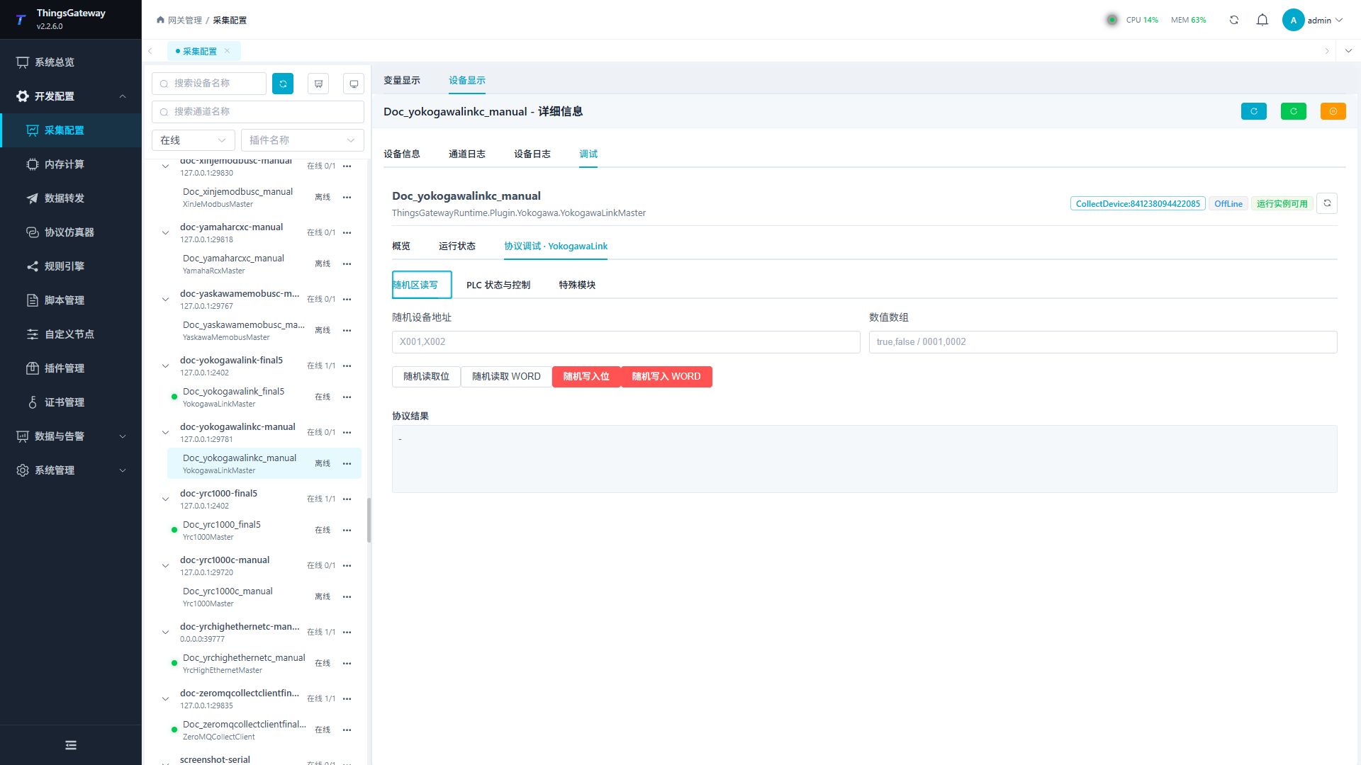
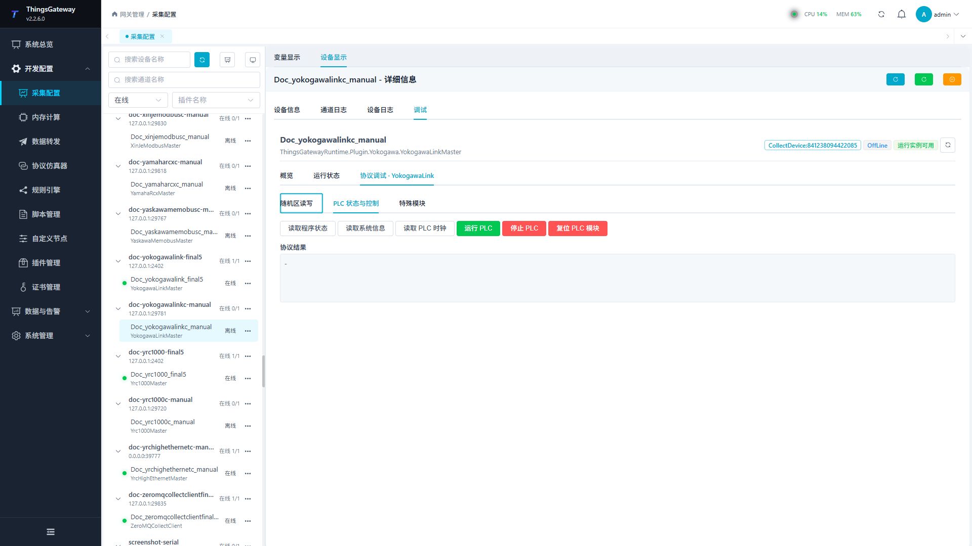
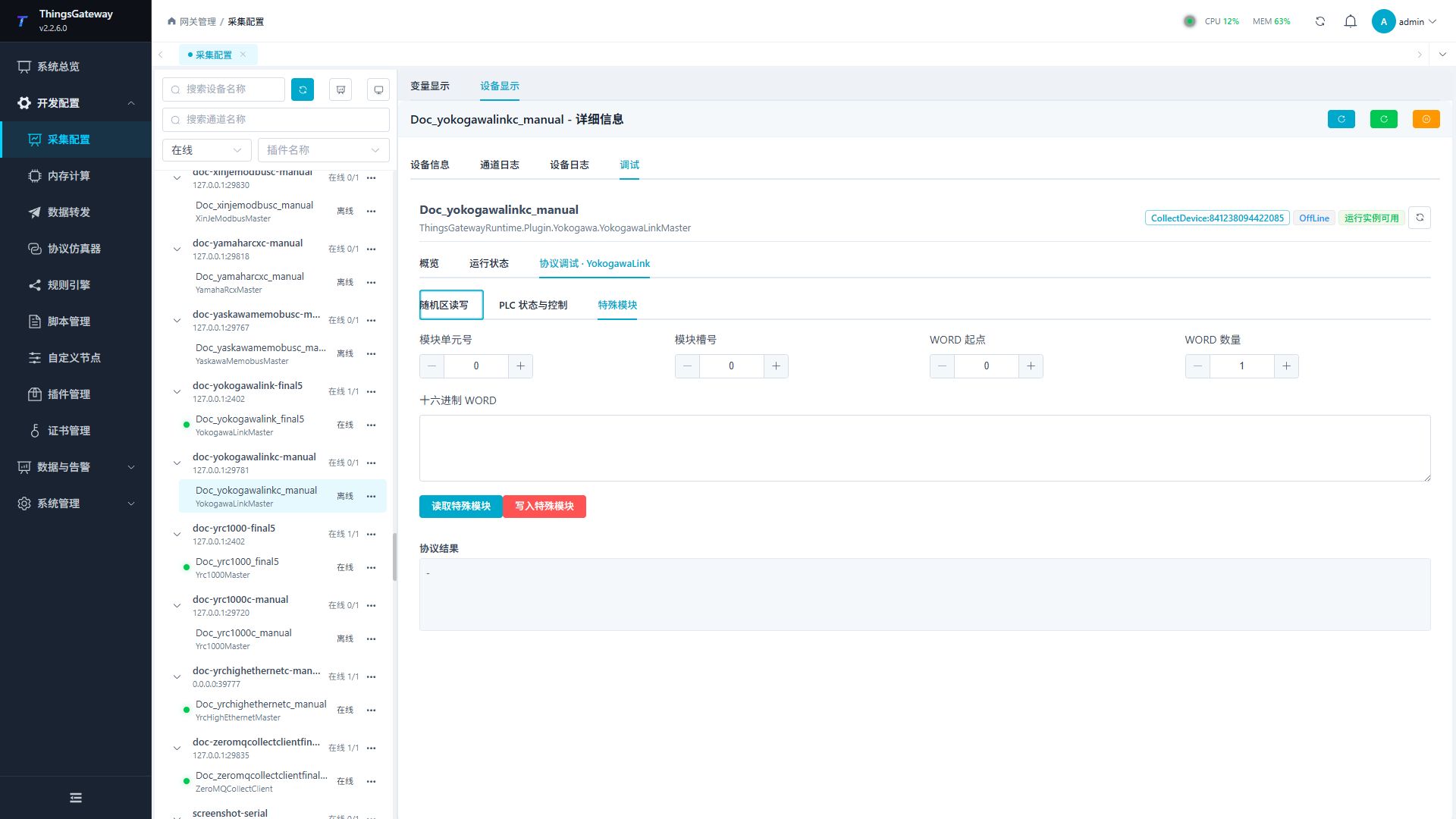
Debugging notes
Read the random area, PLC status, system information and clock first; confirm twice before running/stopping, module reset and random/special module writing.
Functions
| Function | Purpose |
|---|---|
| Random bit/WORD read | Use Random bit/WORD read to inspect mapped values, status, counters, recent messages, or the latest result. |
| Random bit/WORD write | Use Random bit/WORD write with an approved test point and confirm site safety before execution. |
| Program, system, and clock status | Use Program, system, and clock status to inspect mapped values, status, counters, recent messages, or the latest result. |
| Control operation | Use Control operation with an approved test point and confirm site safety before execution. |
| Control operation | Use Control operation with an approved test point and confirm site safety before execution. |
Verify the configuration
Monitor D100 online in the PLC engineering tool, compare its value with the gateway variable and confirm advancing sample times.
Writes and control operations require an approved test point and the site safety procedure.
Troubleshooting
- A request allows 64 WORDs or 256 bits and X is read-only; byte order cannot fix a wrong CPU number.
- Special method execution fails: Check method parameters and permissions; control, write or reset methods also need to confirm that the device is in a state that allows operation.
Related links
- Collection configuration: View channel, device and common variable configuration.
- Plugin Index: Find other collection or data-forward plugins.