On this page
Omron Host Link master
Omron Host Link serial protocol address read and write driver
Open the plugin
Enter “Development Configuration → Collection Configuration”, create a device and select “OmronHostLinkMaster” in “Collection Plugin”.
Supported channels and data types
| Channel type | Pre-configuration check |
|---|---|
| Serial Port | Confirm that the serial port is not occupied by other programs and maintains the same baud rate, data bits, stop bits and parity bits as the device. |
| TCP Client | Confirm network reachability of the device IP, port, and gateway to the device. |
| TCP server | Confirm that the local listening address and port are available, and allow on-site devices to actively connect to the gateway. |
Optional data types: Boolean, Int16, UInt16, Int32, UInt32, Float, String
This list describes types allowed by the plugin editor. Address width, arrays, string length and read/write restrictions still follow this page; it does not mean that every address supports every type.
Plugin properties
Protocol parameters
| Setting | Description |
|---|---|
| PLC station number | Default: 0; fill in: text input. Set the default station number used when the station number is not specified separately in the variable address. |
| Information control field | Default: 0; fill in: text input. Sets the message control fields used for protocol communication. |
| Target unit address | Default: 0; fill in: text input. Sets the target unit address used for protocol communications. |
| Source unit address | Default: 0; fill in: text input. Sets the source unit address used for protocol communications. |
| Service ID | Default: 0; fill in: text input. Set the service ID used for protocol communication. |
| Response waiting characters | Default: 48; fill in: text input. Sets the response wait character used for protocol communication. |
Address rules
- HostLink normal mode address: D, CIO/C, W, H, A, E hexadecimal area code. Address, TIM, CNT, such as D100, CIO20, E1.100.
- The address can use s=2;D100 to overwrite the default station number; the station number ranges from 0 to 255.
- Single continuous read and write up to 260 WORD; bit access uses address.bit number.
- Serial ports typically use 7 data bits, even parity, 1 stop bit; TCP variants use the same line frame.
Device debug
Enter “Development Configuration → Collection Configuration”, select the current device then open “Protocol Debug” at the top of the workspace.
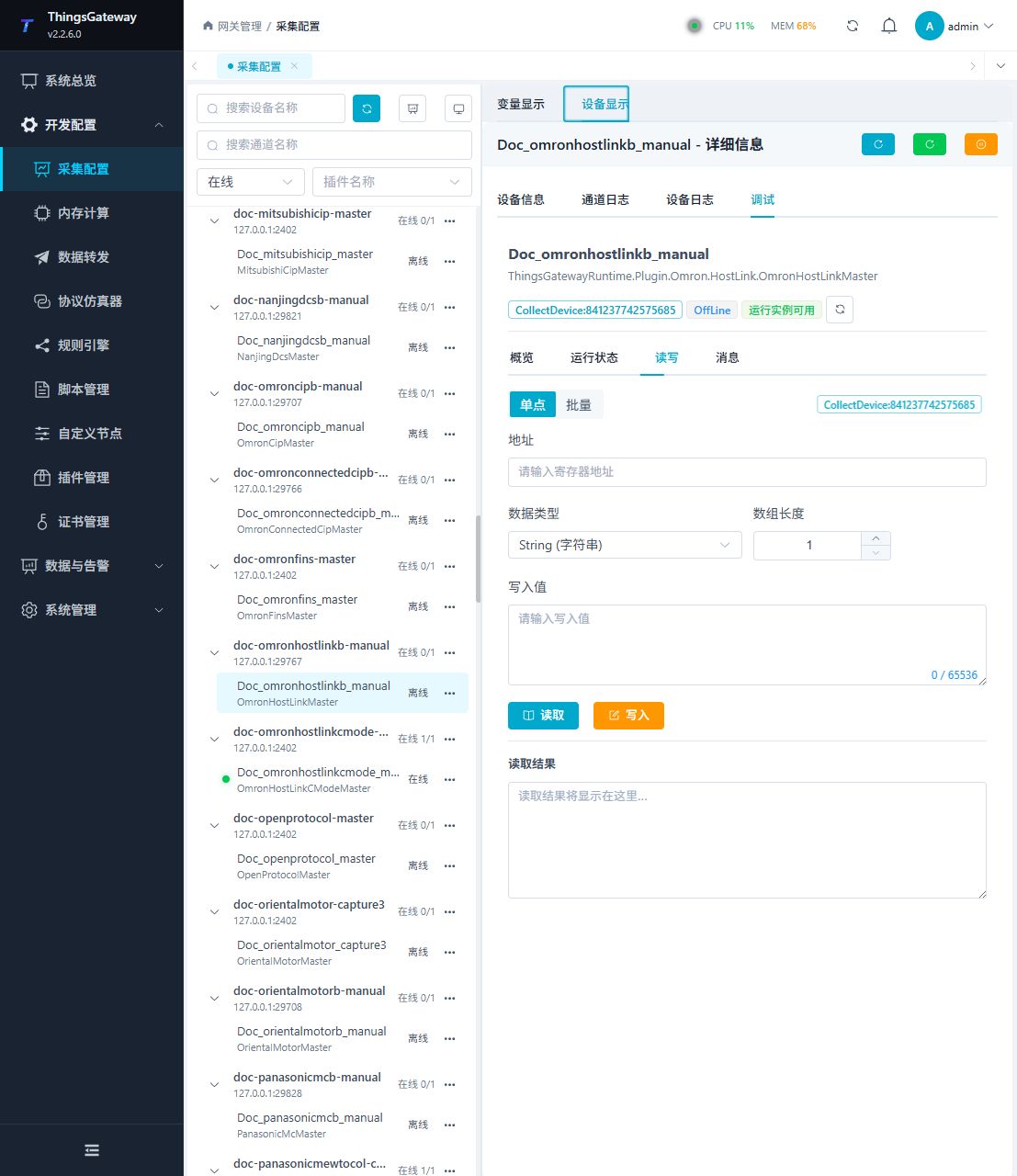
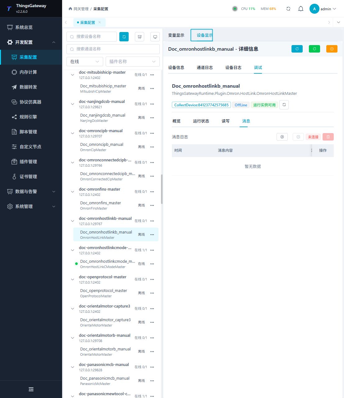
Functions
| Function | Purpose |
|---|---|
| Read and write | Read a confirmed point and write only to an approved test point. |
| Messages | View sent and received frames, protocol fields, and error details. |
Verify the configuration
Monitor D100 online in the PLC engineering tool, compare its value with the gateway variable and confirm advancing sample times.
Troubleshooting
- Limit a request to 260 WORDs and match station, FCS and terminator; do not use FINS TCP frames.
- The serial port device does not respond: Confirm that the serial port is not occupied, and check the baud rate, data bits, stop bits and parity bits.
Related links
- Collection configuration: View channel, device and common variable configuration.
- Plugin Index: Find other collection or data-forward plugins.